Solid electrolyte structure for all-solid-state battery, all-solid-state battery, and their production methods

a technology of solid electrolyte and all-solid-state batteries, which is applied in the field of solid electrolyte structure for all-solid-state batteries and all-solid-state batteries, can solve the problems of insufficient contact area (necking), inability to obtain excellent charge/discharge characteristics, and inability to reduce contact resistance (grain boundary resistance) at the interface, etc., to achieve easy and inexpensive production, excellent charge/discharge characteristics, and reduce contact resistance

Inactive Publication Date: 2009-09-10
NGK INSULATORS LTD +1
View PDF4 Cites 68 Cited by
  • Summary
  • Abstract
  • Description
  • Claims
  • Application Information

AI Technical Summary

Benefits of technology

[0015]The solid electrolyte structure and the all-solid-state battery according to the present invention can show excellent charge / discharge characteristics due to a reduction of contact resistance at the interface between the solid electrolyte and the electrode. Moreover, the stress caused by expansion and contraction of the active material during the charge / discharge process can be effectively dispersed and reduced.
[0016]The method of producing a solid electrolyte structure and the method of producing an all-solid-state battery according to the present invention can produce the solid electrolyte structure and the all-solid-state battery to produce easily and inexpensively.

Problems solved by technology

According to the method of producing the all-solid-state battery disclosed in Patent Document 2, if the active material and the solid electrolyte differ in sintering temperature, the contact resistance (grain boundary resistance) at the interface cannot be reduced so that excellent charge / discharge characteristics cannot be obtained.
However, since the active material and the solid electrolyte differ in sintering temperature, a sufficient contact area (necking) cannot be formed when the material has a high sintering temperature.
As a result, the performance of the active material deteriorates so that the charge / discharge capacity may decrease or the reaction resistance may increase.
On the other hand, since the stress due to expansion and contraction directly acts on the interface between the electrode and the electrolyte of the all-solid-state battery, cracks and the like occur at the interface between the electrode and the electrolyte so that delamination occurs.
As a result, the charge / discharge operation is hindered.
When delamination occurs to a larger extent, the function of the battery is impaired.

Method used


Image

  • Solid electrolyte structure for all-solid-state battery, all-solid-state battery, and their production methods
  • Solid electrolyte structure for all-solid-state battery, all-solid-state battery, and their production methods
  • Solid electrolyte structure for all-solid-state battery, all-solid-state battery, and their production methods

Examples


example 1

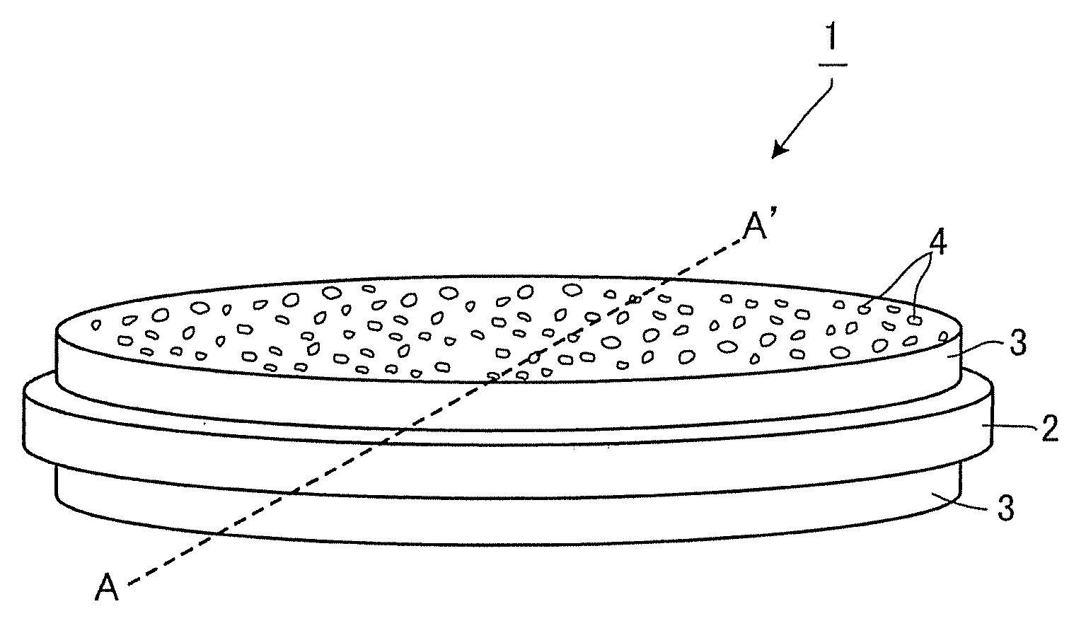
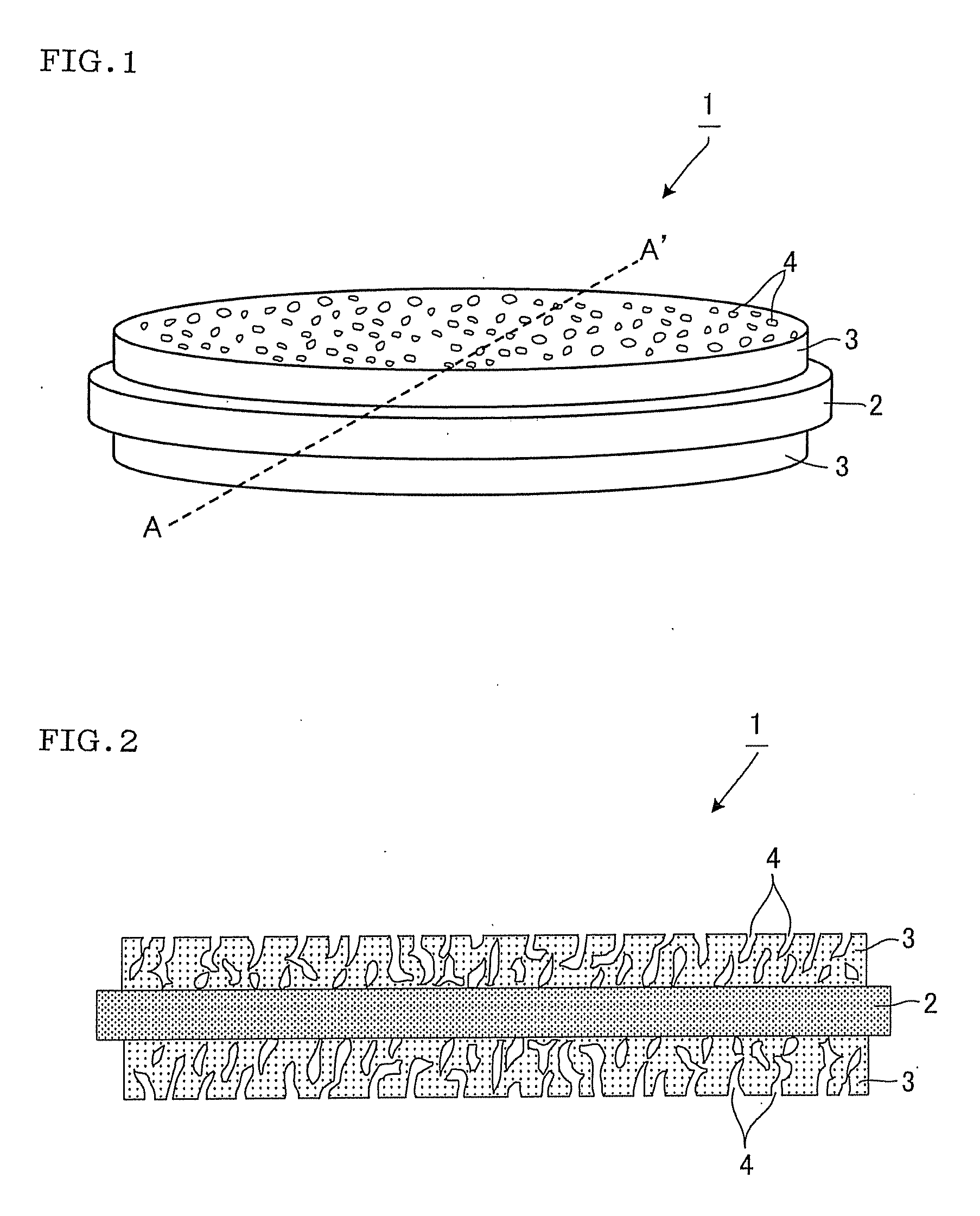
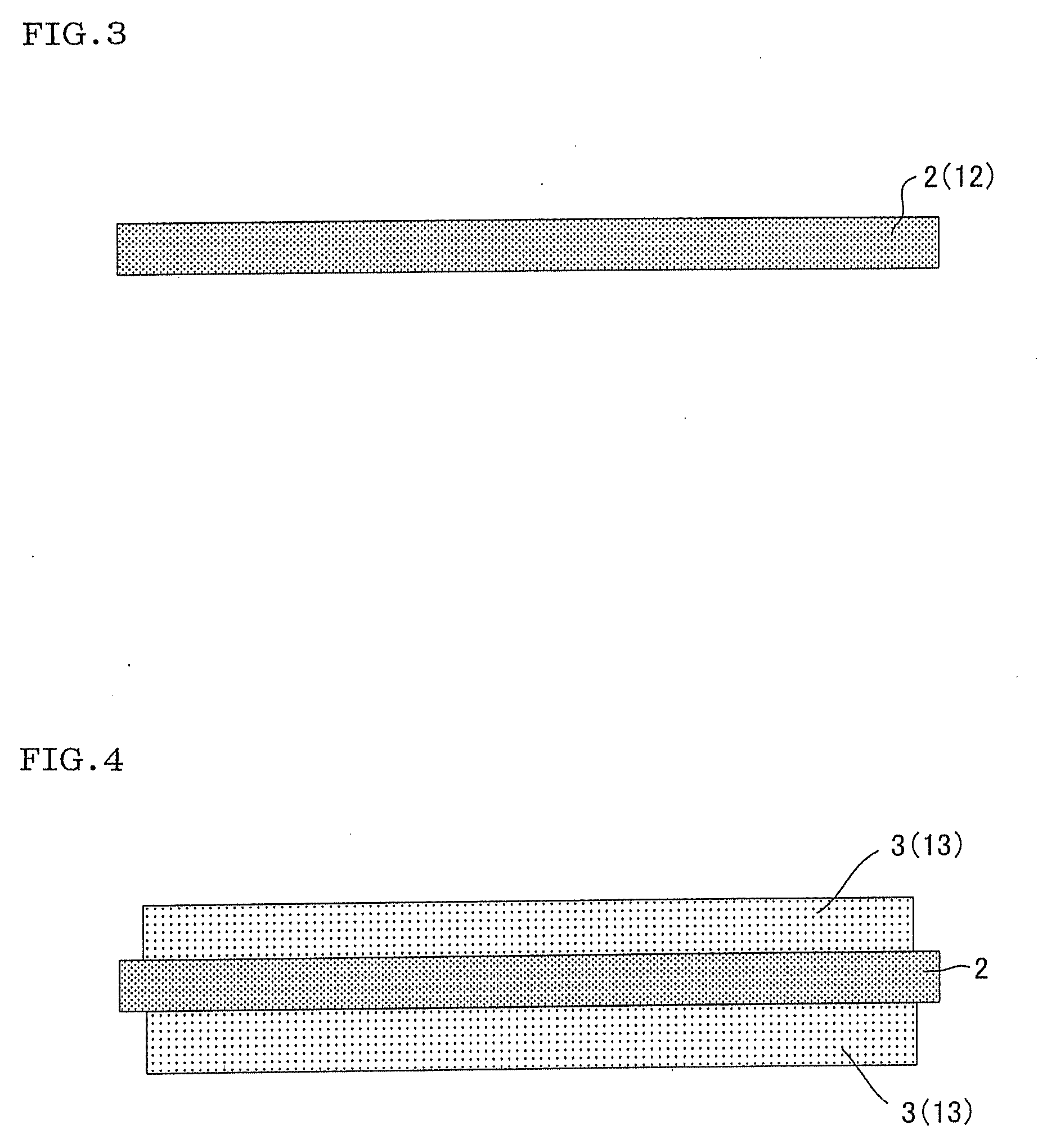
[0093]An Li0.35La0.55TiO3 (solid electrolyte) powder (first ceramic material) was formed with a press-mold to obtain a first formed body having a diameter of about 13 mm and a thickness of 1 mm (dimensions after firing). The first formed body was fired at 1150° C. in air to obtain a dense body.

[0094]A screen printing paste (second ceramic material) was prepared using a solid electrolyte powder having the same composition as that of the solid electrolyte used for the first formed body. In this example, S-LEC B (manufactured by Sekisui Chemical Co., Ltd.) (binder), CS-12 (manufactured by Chisso Corporation) (organic solvent), and theobromine (pore-forming agent) were added to the solid electrolyte powder when preparing the screen printing paste corresponding to the design of pores formed in a porous layer. The screen printing paste was applied to the surface of the dense body by a screen printing method to obtain a second formed body having a diameter of about 12 mm and a thickness of...

example 2

[0101]An all-solid-state battery (Example 2) was produced in the same manner as in Example 1, except that the screen printing paste (second ceramic material) used to form the porous layer of the solid electrolyte structure was prepared using the solid electrolyte powder, S-LEC B (manufactured by Sekisui Chemical Co., Ltd.) (binder), and CS-12 (manufactured by Chisso Corporation) (organic solvent) so that the porous layer had a porosity lower than that of the porous layer of Example 1 and the pore size of the pores was smaller than that of the porous layer of Example 1. FIG. 8 shows an SEM photograph of the cross section of the dense body 2 and the porous layer 3 of the solid electrolyte structure 1 produced in Example 2.

example 3

[0102]An Li1.5Al0.5Ge1.5(PO4)3 (solid electrolyte) powder (first ceramic material) was formed with a press-mold to obtain a first formed body having a diameter of about 13 mm and a thickness of 1 mm (dimensions after firing). The first formed body was fired at 840° C. in air to obtain a dense body.

[0103]A screen printing paste (second ceramic material) was prepared using a solid electrolyte powder having the same composition as that of the solid electrolyte used for the first formed body. In this example, S-LEC B (manufactured by Sekisui Chemical Co., Ltd.) (binder), CS-12 (manufactured by Chisso Corporation) (organic solvent), and theobromine (pore-forming agent) were added to the solid electrolyte powder when preparing the screen printing paste corresponding to the design of pores formed in a porous layer. The screen printing paste was applied to the surface of the dense body by a screen printing method to obtain a second formed body having a diameter of about 12 mm and a thicknes...


PUM

PropertyMeasurementUnit
thicknessaaaaaaaaaa
thicknessaaaaaaaaaa
thicknessaaaaaaaaaa

Abstract

A solid electrolyte structure (1) for all-solid-state batteries includes a plate-like dense body (2) formed of a ceramic that includes a solid electrolyte, and a porous layer (3) formed of a ceramic that includes a solid electrolyte that is the same as or different from the solid electrolyte of the dense body (2), the porous layer (3) being integrally formed on at least one surface of the dense body (2) by firing. The solid electrolyte structure can reduce the contact resistance at the interface between the solid electrolyte and an electrode.

Description

TECHNICAL FIELD[0001]The present invention relates to a solid electrolyte structure for all-solid-state batteries, an all-solid-state battery, and methods of producing the same. More particularly, the present invention relates to a solid electrolyte structure for all-solid-state batteries that can reduce the contact resistance at the interface between the solid electrolyte and an electrode, an all-solid-state battery using the solid electrolyte structure, and methods of producing the same.BACKGROUND ART[0002]In recent years, along with the remarkable development of portable instruments such as personal computers and portable telephones, batteries used to supply power to such portable instruments have been in great demand. In a battery used in such applications, a liquid electrolyte (electrolytic solution) utilizing a flammable organic solvent (dilution solvent) has been used as a medium through which ions move. A battery that utilizes such an electrolytic solution may ignite or expl...

Claims


Application Information

Patent Timeline
Patent Type & Authority Applications(United States)
IPC IPC(8): H01M6/18C04B35/64B05D5/12H01M4/13H01M10/0562H01M10/36
CPCH01M4/13H01M10/0562H01M2300/0071H01M2300/0094Y02E60/122C04B2235/3287C04B35/462C04B2235/3203C04B2235/3217C04B2235/3227C04B35/447Y02E60/10Y02P70/50
Inventor YOSHIDA, TOSHIHIROYAMAMOTO, KAZUHIROKANAMURA, KIYOSHI
Owner NGK INSULATORS LTD
Why Eureka
Try Eureka