Guide wire with core having welded wire segments

a technology of guide wire and welded wire segments, which is applied in the direction of guide wires, catheters, diagnostic recording/measure, etc., can solve the problems of difficult if not impossible direct welding of stainless steel to nitinol, and achieve the effect of improving the overall torqueability and pushability of the guide wire, enhancing compressive, tension and torsion strength, and different structural and strength characteristics and advantages

Active Publication Date: 2009-09-10
ABBOTT CARDIOVASCULAR
View PDF27 Cites 24 Cited by
  • Summary
  • Abstract
  • Description
  • Claims
  • Application Information

AI Technical Summary

Benefits of technology

[0010]Accordingly, in each embodiment of the present invention, a transition piece formed essentially of nickel is utilized to effect the connection between the stainless steel proximal portion and the nitinol distal portion, as it appears that nickel will form a welded bond with both stainless steel and nitinol, without cracking or metal property alteration taking place at the boundaries between the welded metals. The preferred composition of the transition piece is effectively pure nickel, although alloying with different metals may be permitted to the extent that (a) this does not interfere with the ability of the resulting composition to form an essentially crack-free bond with the adjacent stainless steel and nitinol portions or (b) does not cause the melting temperature of the resulting composition to be elevated to a point where the heat required to form the weld removes or diminishes the unique characteristics of nitinol. In the preferred embodiment, welding may be performed by known methods of laser or friction welding, although other known forms of microwelding such as electron beam welding, and plasma arc welding may be used.
[0011]In different embodiments, the geometry of the transition piece may differ to provide different structural and strength characteristics and advantages, as desired. In a first embodiment, the transition piece has a simpl

Problems solved by technology

As noted above, it is known that direct welding of stainless steel to nitinol is difficult if not impossible, in that atte

Method used


Image

  • Guide wire with core having welded wire segments
  • Guide wire with core having welded wire segments
  • Guide wire with core having welded wire segments

Examples


Embodiment Construction

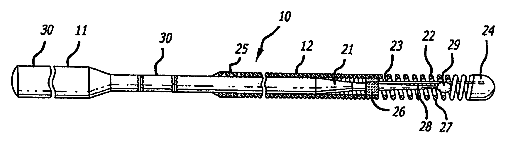
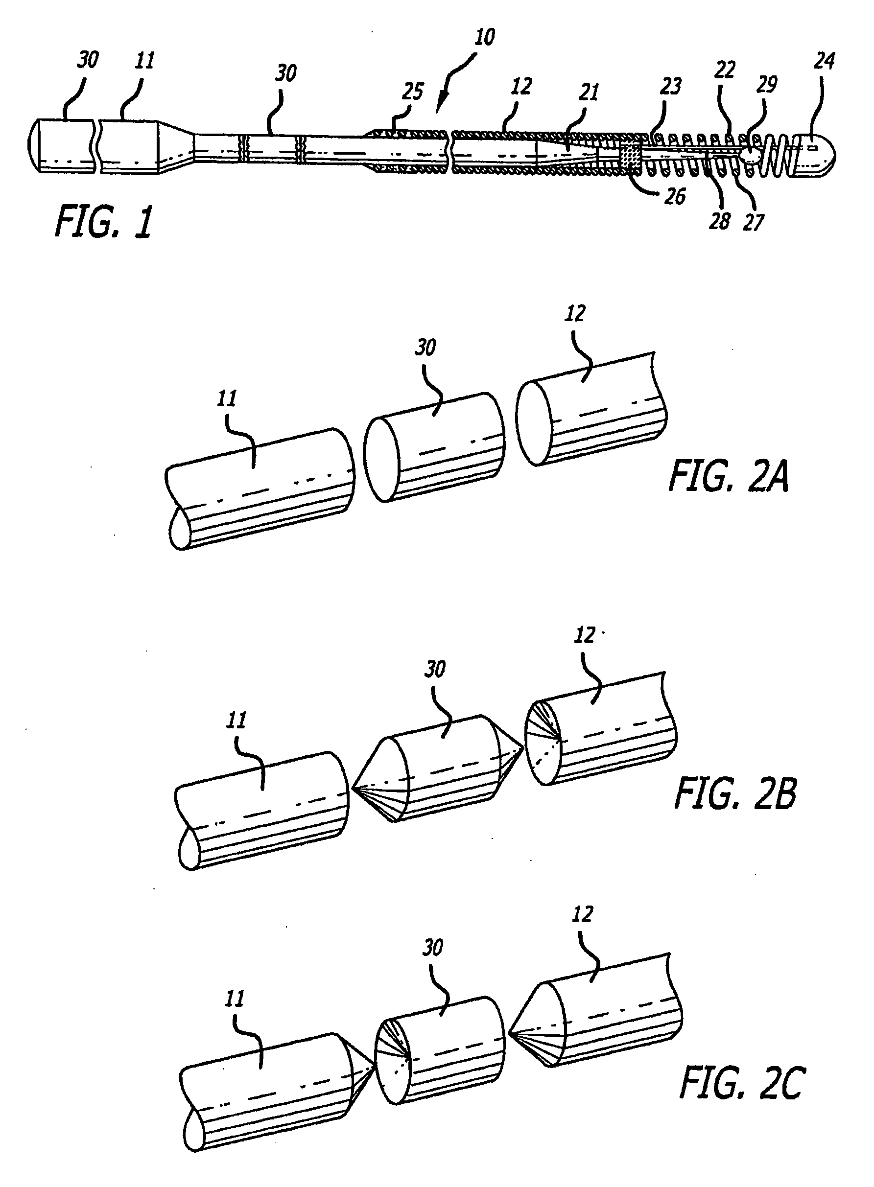
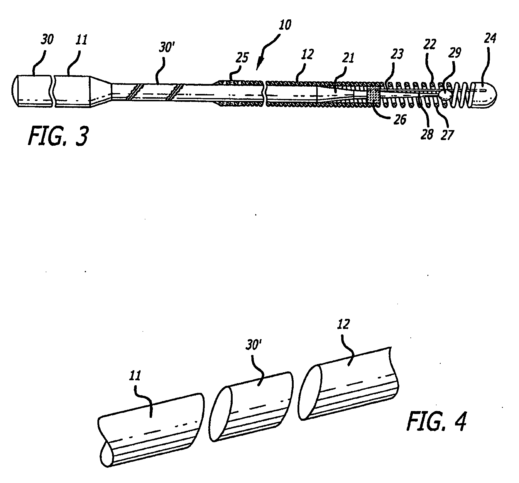
[0028]FIG. 1 illustrates a guide wire 10 embodying features of the invention that is adapted to be inserted into a patient's body lumen, such as an artery or vein. The guide wire 10 comprises an elongated, relatively high strength proximal core section 11, and a relatively short flexible distal core section 12. The distal core portion 12 has at least one tapered section 21 which becomes smaller in the distal direction. A helical coil 22 is disposed about the distal core section 12 and is secured by its distal end to the distal end of shaping ribbon 23 by a mass of solder which forms rounded plug 24 when it solidifies. The proximal end of the helical coil 22 is secured to the distal core section 12 at a proximal location 25 and at intermediate location 26 by a suitable solder. The proximal end of the shaping ribbon 23 is secured to the distal core portion 12 at the same intermediate location 26 by the solder. Preferably, the most distal section 27 of the helical coil 22 is made of ra...


PUM


Abstract

An intravascular guide wire having two core materials joined together without the use of a connector tube or sleeve, the core materials being stainless steel and psuedoelastic metal alloy, nitinol. The core materials are joined to each other through an intermediate transition piece made essentially of nickel, which is welded on either side to the two core materials. In a multi-segment intravascular guide wire, discrete, high modulus and medium modulus core portions of different materials are welded to a shapeable, low modulus distal core portion made of a third material having a flattened, shapeable section at a most distal end that is not welded to but made from the distal core portion, so the flattened, shapeable section can be deformed to create a steerable tip. Processes such as simultaneous resistance and friction welding can be used to join the core portions.

Description

CROSS-REFERENCE TO RELATED APPLICATIONS[0001]This application is a continuation-in-part (CIP) of co-pending U.S. application Ser. No. 10 / 930,458, filed Aug. 31, 2004, titled “Apparatus and Method for Joining Stainless Steel Guide Wire Portion to Nitinol Portion, Without a Hypotube,” the entire contents of which are hereby incorporated by reference.FIELD OF THE INVENTION[0002]This invention relates to the field of medical devices, and more particularly to a guide wire for advancing a catheter within a body lumen in a procedure such as percutaneous transluminal coronary angioplasty (PTCA).BACKGROUND OF THE INVENTION[0003]In a typical PTCA procedure, a guiding catheter having a preformed distal tip is percutaneously introduced into a patient's peripheral artery, e.g. femoral or brachial artery, by means of a conventional Seldinger technique and advanced therein until the distal tip of the guiding catheter is seated in the ostium of a desired coronary artery. A guide wire is first advan...

Claims


Application Information

Patent Timeline
IPC IPC(8): A61M25/01
CPCA61M2025/09108A61M2025/09133B23K15/0046B23K11/02B23K26/20Y10T29/49826A61M2025/09083B23K20/129A61M2025/09141A61M25/09A61M25/0009B23K26/26B23K26/282
Inventor SIMPSON, JOHN A.PLATTNER, MICHAELMANNING, FRANKGRANDFIELD, RYANCORNISH, WAYNE E.
Owner ABBOTT CARDIOVASCULAR
Why Eureka
Try Eureka