Photonic milling using dynamic beam arrays

a beam array and photonic technology, applied in metal-working equipment, welding equipment, manufacturing tools, etc., can solve the problems of difficult to take the most advantage of forthcoming high-precision lasers, complex laser optical sub-assemblies of dual-beam and multi-beam laser systems, and high cost of construction

Inactive Publication Date: 2009-10-01
ELECTRO SCI IND INC
View PDF35 Cites 44 Cited by
  • Summary
  • Abstract
  • Description
  • Claims
  • Application Information

AI Technical Summary

Benefits of technology

[0017]Additional aspects and advantages will be apparent from the following detailed description of preferred embodiments, which proceeds with reference to the accompanying drawings.

Problems solved by technology

Because faulty memory cells needing link removals may be randomly located, workpiece positioning delay times typically require that such laser repair processes be performed over a wide range of interpulse times, rather than at a single interpulse time.
Thus, it may be difficult to take the most advantage of forthcoming high PRF lasers (e.g., PRFs in the hundreds of kHz or MHz ranges).
Dual-beam and multi-beam laser systems generally use complex laser optical subassemblies and are generally expensive to construct.
Further, recent advances in laser design present problems with this approach.
However, in a passively mode-locked master oscillator, the output frequency may not be so easily modified.
However, achieving such beam position timing while maintaining pulse placement accuracy may be quite difficult.
Servo control systems typically cannot guarantee high-accuracy (e.g., within 10 nm) pulse placement within such small, fixed timing windows.
While the timing precision is used to maintain the accuracy of the processing system, the arbitrary timing of pulse commands can degrade aspects of laser performance, such as pulse width and peak power.
However, such lasers may be sensitive to the value of (and variation in) the interpulse period.

Method used


Image

  • Photonic milling using dynamic beam arrays
  • Photonic milling using dynamic beam arrays
  • Photonic milling using dynamic beam arrays

Examples


Embodiment Construction

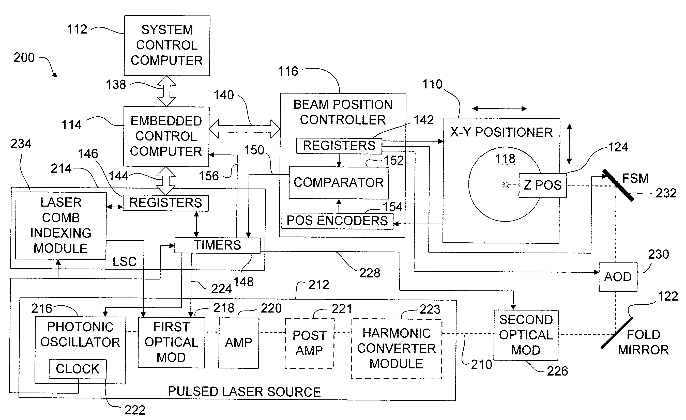
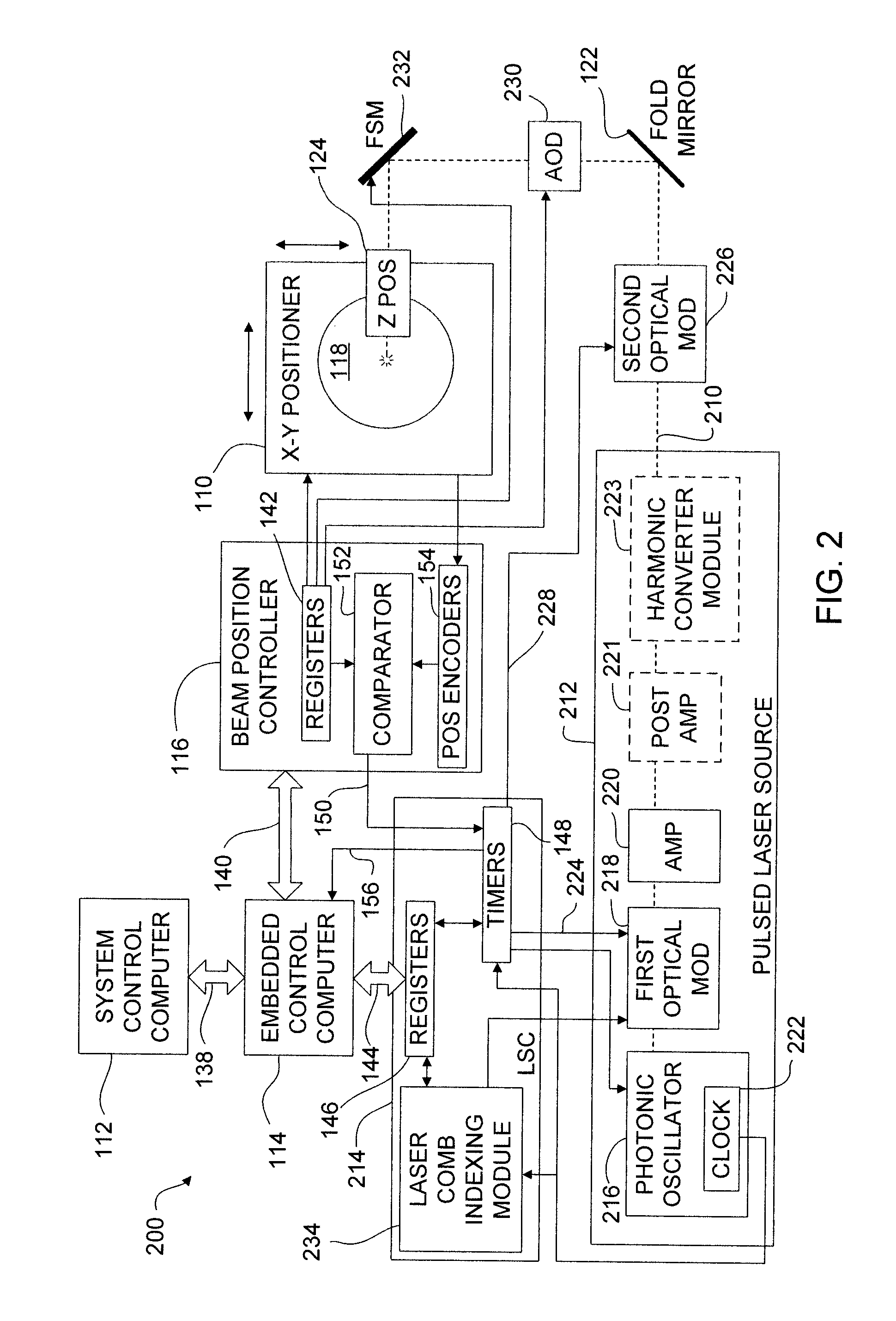
[0039]In one embodiment, a photonic clock is used as a master timing element to coordinate beam positioner control elements in a laser processing system. The photonic clock may be a pulsed output from a photonic oscillator in a pulsed laser source. The photonic oscillator may be a seed oscillator or a master oscillator. The beam positioner control elements use timing signals from the photonic oscillator to synchronize the alignment of target structures on a workpiece with the emission of laser pulses from the laser system. One or more pulses from the laser source are transmitted through the optical elements of a laser system to process the target structures. Pulses from the laser source may be amplitude divided to create arrays of pulses for processing the target structures.

[0040]The laser systems and methods disclosed herein may be used to process a wide variety of workpiece targets. For example, certain embodiments may be used to sever electrically conductive link structures in a ...


PUM

PropertyMeasurementUnit
timeaaaaaaaaaa
timeaaaaaaaaaa
wavelengthaaaaaaaaaa

Abstract

A laser processing system includes a beam positioning system to align beam delivery coordinates relative to a workpiece. The beam positioning system generates position data corresponding to the alignment. The system also includes a pulsed laser source and a beamlet generation module to receive a laser pulse from the pulsed laser source. The beamlet generation module generates a beamlet array from the laser pulse. The beamlet array includes a plurality of beamlet pulses. The system further includes a beamlet modulator to selectively modulate the amplitude of each beamlet pulse in the beamlet array, and beamlet delivery optics to focus the modulated beamlet array onto one or more targets at locations on the workpiece corresponding to the position data.

Description

RELATED APPLICATION [0001]This application is a continuation-in-part of U.S. patent application Ser. No. 12 / 060,199, titled “PHOTONIC CLOCK STABILIZED LASER COMB PROCESSING,” filed Mar. 31, 2008, which is hereby incorporated by reference herein in its entirety.TECHNICAL FIELD [0002]This disclosure relates to laser processing systems. In particular, this disclosure relates to systems and methods for synchronizing selection of pulses for amplification and alignment with workpiece targets based on a photonic clock and position data.BACKGROUND INFORMATION [0003]Lasers may be used in a variety of industrial operations including inspecting, processing, and micro-machining substrates, such as electronic materials. For example, to repair a dynamic random access memory (“DRAM”), a first laser pulse is used to remove an electrically conductive link to a faulty memory cell of a DRAM device, and then a second laser pulse is used to remove a resistive link to a redundant memory cell to replace t...

Claims


Application Information

Patent Timeline
Patent Type & Authority Applications(United States)
IPC IPC(8): B23K26/00
CPCB23K26/03B23K26/0622B23K26/046
Inventor BAIRD, BRIAN W.BRULAND, KELLY J.HAINSEY, ROBERT
Owner ELECTRO SCI IND INC
Why Eureka
Try Eureka