Polarization Optical Time Domain Reflectometer and Method of Determining PMD

a reflectometer and optical time domain technology, applied in the direction of reflectometers dealing with polarization, amplifiers, transmission, etc., can solve the problems of increasing bit error rate, limiting the transmission rate or maximum transmission path length, and particularly problematic at higher bit ra

Inactive Publication Date: 2009-10-01
EXFO ELECTRO OPTICAL ENG
View PDF7 Cites 16 Cited by
  • Summary
  • Abstract
  • Description
  • Claims
  • Application Information

AI Technical Summary

Benefits of technology

[0028]The present invention seeks to eliminate, or at least mitigate, the disadvantages of the prior art discussed above, or at least provide an alternative. To this end, in a method of measuring cumulative polarization mode dispersion (PMD) along the length of a fiber-under-test (FUT), a single-end polarization sensitive optical time domain reflectometer (POTDR) is used to inject into the FUT plural series of light pulses arranged in several groups. Each group comprises at least two series of light pulses having different but closely-spaced wavelengths and the same SOP. At least two, and preferably a large number of such groups, are injected and corresponding OTDR tr...

Problems solved by technology

This causes the polarization mode dispersion (PMD) phenomenon, i.e., a spreading of the pulses propagating along the fibers Where long optical fiber links are involved, overall PMD may be sufficient to cause increased bit error rate, thus limiting the transmission rate or maximum transmission path length.
This is particularly problematical at higher bit rates.
As explained in commonly-owned U.S. Pat. No. 6,724,469 (Leblanc), in optical communication systems, an unacceptable overall polarization mode dispersion (PMD) level for a particular long optical fiber may be caused by one or more short sections of the overall optical fiber link.
A general limitation of all the techniques of this first type, therefore, is that they do not provide a direct, reliable, valid in all cases and quantitative measurement of PMD with respect to distance along the optical fiber.
Notably, twisted fibers like modern spun fibers already require some special models, which implies that an instrument must know in advance the type and characteristics of the FUT, which is unacceptable for a commercial instrument.
In practice, although they can measure birefringence quantitatively (cf. F. Corsa et al. supra), or statistically screen high birefringence sections (Chen et al. supra), or obtain qualitative and relative estimates of the PMD of short sections provided that one accept frequently occurring exceptions (Leblanc, Huttner, supra), POTDR techniques of this first type cannot reliably and quantitatively measure PMD, particularly of unknown, mixed installed fibers in the fie
ld. Furthermore, they are incapable of inferring, even approximately, the overall PMD of a long length of fiber, such as for example 10 kilomet
However, this technique also suffers from the fundamental limitations associated with this type, as mention...

Method used


Image

  • Polarization Optical Time Domain Reflectometer and Method of Determining PMD
  • Polarization Optical Time Domain Reflectometer and Method of Determining PMD
  • Polarization Optical Time Domain Reflectometer and Method of Determining PMD

Examples


Embodiment Construction

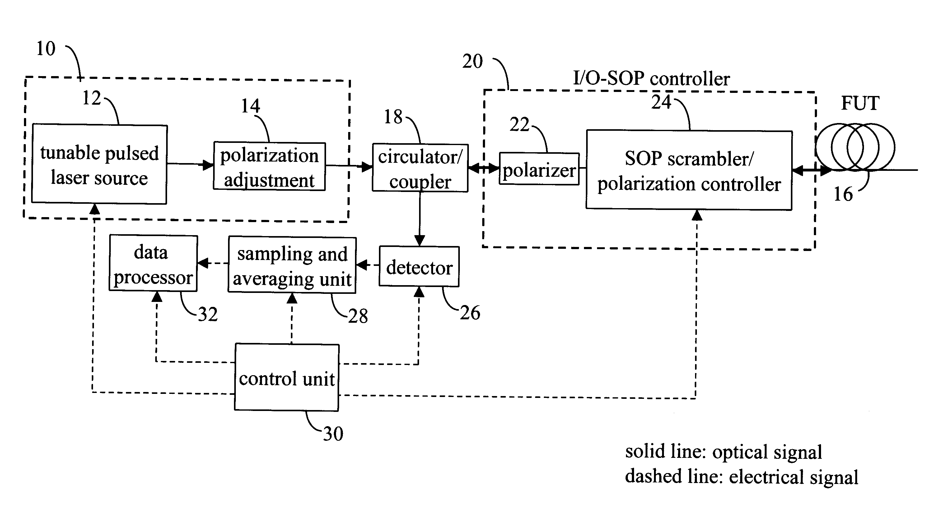
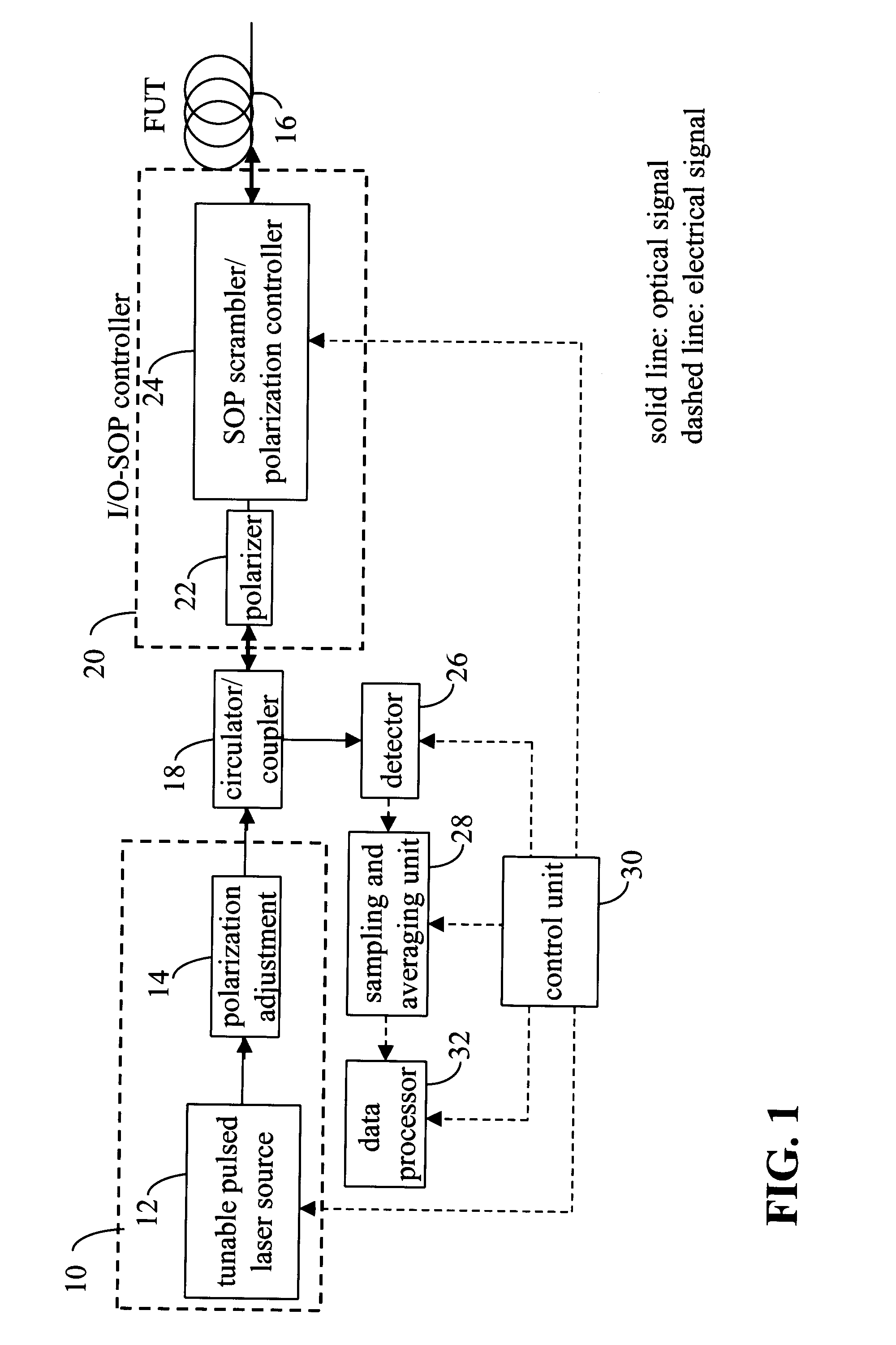
[0050]The quantitative polarization time domain reflectometer (POTDR) 10 illustrated in FIG. 1 comprises tunable light source means 10 in the form of a tunable laser source 12 and polarization state adjuster 14 for launching light pulses into a fiber-under-test (FUT) 16 via a circulator 18 and polarization control means 20 which comprises a polarizer 22 and a polarization controller 24. It should be noted that the polarization state adjuster is normally “factory set” to maximize the transmission of the light pulses through the polarizer 22 and should not normally need to be subsequently re-adjusted. For convenience, the polarization control means 20 will be referred to as an input / output SOP controller (I / O-SOP). Resulting backreflected light caused by Rayleigh scattering and / or discrete reflections from the (FUT) 16 passes through the I / O-SOP controller 20 in the reverse direction and is conveyed by the circulator 18 to a photodetector 26. The corresponding electrical signal is sam...


PUM


Abstract

In a method of measuring cumulative polarization mode dispersion (PMD) along the length of a fiber-under-test (FUT), a polarization-sensitive optical time domain reflectometer (POTDR) is used to inject into the FUT plural series of light pulses arranged in several groups. Each group comprises at least two series of light pulses having different but closely-spaced wavelengths and the same state of polarization (SOP). At least two, and preferably a large number of such groups, are injected and corresponding OTDR traces obtained for each series of light pulses by averaging the impulse-response signals of the several series of light pulses in the group. The process is repeated for a large number of groups having different wavelengths and/or SOPs. The PMD then is obtained by normalizing the OTDR traces of all of the groups, then computing the difference between each normalized OTDR trace in one group and the corresponding normalized OTDR trace in another group, followed by the mean-square value of the differences. Finally, the PMD is computed as a predetermined function of the mean-square difference. The function may, for example, be a differential formula, an arcsine formula, and so on.

Description

CROSS-REFERENCE TO RELATED DOCUMENTS[0001]This application claims priority from U.S. Provisional patent application No. 60 / 721,532 filed Sep. 29, 2006, the entire contents of which are incorporated herein by reference.[0002]The present application is related to Disclosure Document No. 564,640 entitled “Robust Accumulated Polarization Mode Dispersion Measurements by Use of a Single End OTDR Technique, filed in the United States Patent and Trademark Office on Nov. 9, 2004. The entire contents of this Disclosure Document are incorporated herein by reference.TECHNICAL FIELD[0003]The invention relates to a method and apparatus for measuring polarization-dependent characteristics of optical paths and is especially applicable to so-called polarization optical time domain reflectometers, and corresponding methods, for measuring polarization mode dispersion (PMD) of an optical path which comprises mostly optical waveguide, such as an optical fiber link.BACKGROUND ART[0004]In optical fibers u...

Claims


Application Information

Patent Timeline
IPC IPC(8): G01N21/00G06F15/00
CPCG01M11/3181
Inventor CYR, NORMANDCHEN, HONGXIN
Owner EXFO ELECTRO OPTICAL ENG
Why Eureka
Try Eureka