Optical apparatus, photomask inspecting apparatus, and exposure apparatus

Inactive Publication Date: 2009-10-01
KK TOPCON
View PDF8 Cites 7 Cited by
  • Summary
  • Abstract
  • Description
  • Claims
  • Application Information

AI Technical Summary

Benefits of technology

[0029]As the division number of the integrator is increased, the Fresnel number of each lens element of the integrator is decreased, whereby the light concentrating effect of the lens elements is reduced, and effects of boundaries of lens elements of the integrator are increased. Therefore, the effect of increasing the division number is limited. That is, the division number of the integrator cannot be greatly increased, and there is an upper limit in practical use. The inequality in the left side in the numerical formula (2) defines the upper limit.
[0030]In a case of obtaining a predetermined division number by serially arranging plural integrators, optical design may be performed based on the following design guide. In this case, first, optical design is performed by assuming use of one integrator, and an upper limit of a division number N of the integrator is calculated by using the inequality in the left side in the above numerical formula (2). Next, a division number N satisfying the above numerical formula (2) is selected within the above upper limit, and a combination of plural integrat

Problems solved by technology

However, even when the above-described techniques are used, it is difficult to reduce the generation of the ghost images to such a degree that the effects of th

Method used


Image

  • Optical apparatus, photomask inspecting apparatus, and exposure apparatus
  • Optical apparatus, photomask inspecting apparatus, and exposure apparatus
  • Optical apparatus, photomask inspecting apparatus, and exposure apparatus

Examples


Example

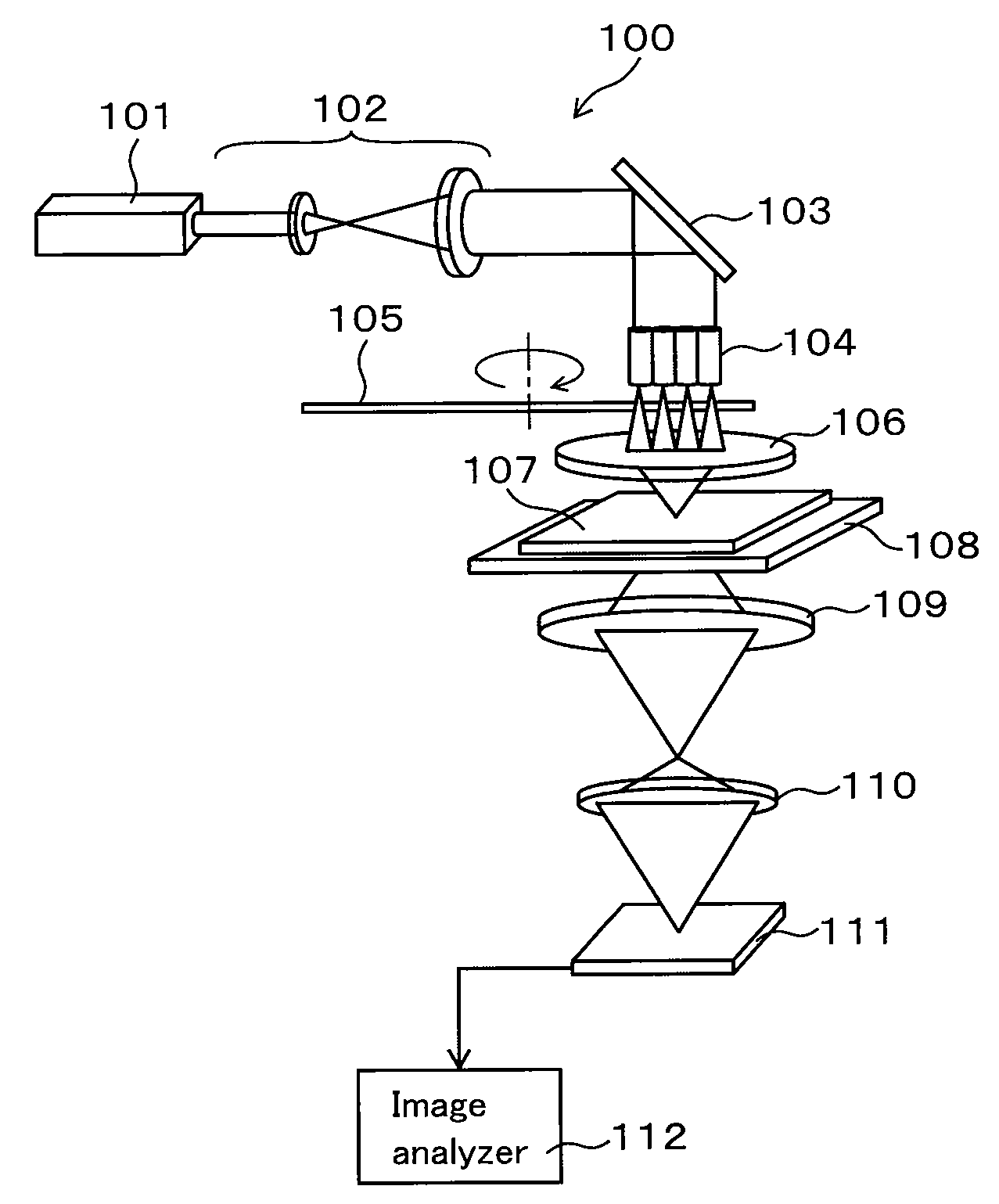
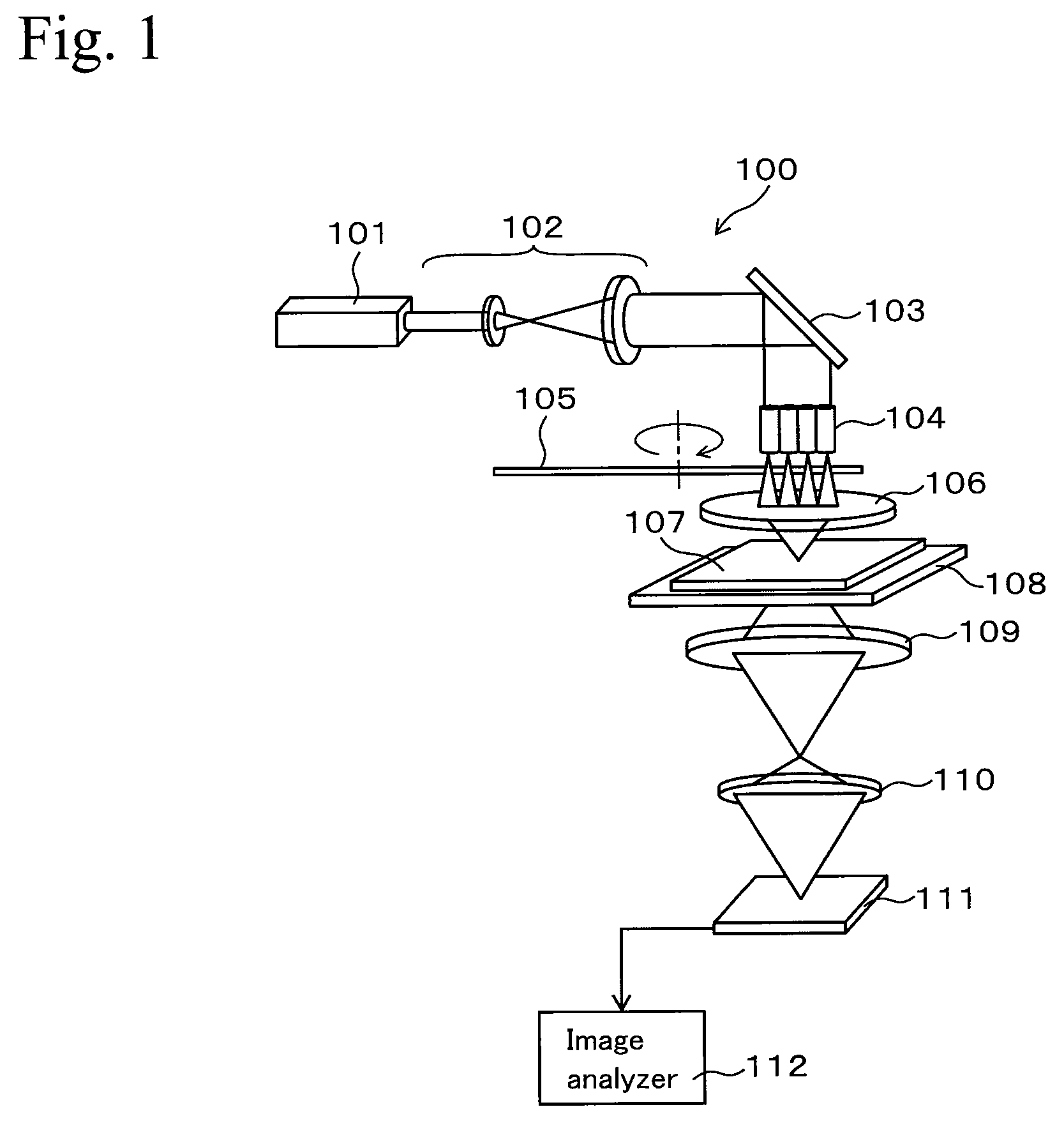
[0040]In the first embodiment, an example of an optical apparatus (a photomask inspecting apparatus) for inspecting defects of an attenuated phase-shift mask is described. FIG. 1 is a schematic view showing an example of a photomask inspecting apparatus using the present invention.

[0041]FIG. 1 shows a photomask inspecting apparatus 100 having a CW oscillation type laser light generating device 101 as a laser light source. The laser light generating device 101 outputs a laser light in the ultraviolet. For example, a device, which continuously oscillates a second harmonic wave having a wavelength of 257 nm of an argon ion laser, may be used as the laser light generating device 101. Although the wavelength of the wave is not limited thereto, the wavelength is preferably the same as that of exposure light used for inspecting a photomask.

[0042]Laser light is output from the laser light generating device 101 and is shaped into a beam by a beam expander 102, and the beam enters a fly-eye l...

Example

(2) Second Embodiment

[0085]The optical apparatus shown in FIG. 1 may be used for an exposure apparatus using a laser light source. In this case, an X-Y stage is placed at the position of the image sensor 111, and a sample to be exposed is arranged on the stage, whereby the sample is exposed. The variable magnification optical system 110 is changed to a demagnifying optical system, so that a pattern of a photomask is reduced in size and is irradiated on the sample.

[0086]In a case of using the apparatus in FIG. 1 for an exposure apparatus, when an attenuated phase shift mask is used as a photomask, ghost images occur in an exposed area (an area illuminated with laser light), but the contrast of the ghost images can be sufficiently small for the reason described in the first embodiment. Therefore, the generation of defects due to effects of ghost images is prevented in an exposure step. Since uneven distribution of irradiation intensity of exposure light to be irradiated on a photomask...


PUM


Abstract

An optical apparatus includes a laser light source for emitting a beam of light, an integrator for dividing the beam of light into plural beams of light, and a light focusing optical system for focusing the beams of light passed through the integrator. The optical apparatus also includes a stage, on which the light concentrated by the light focusing optical system is irradiated and on which an object may be placed, and includes a projecting optical system for projecting the light transmitted through the object. The following conditions satisfy the following numerical formula (1). The projecting optical system has a visual field including an effective visual field, and the integrator has a division number N corresponding to a predetermined direction in a predetermined effective visual field. A ghost image is formed in the effective visual field in the predetermined direction and has contrast γ. The light focusing optical system has numerical aperture NA1, the projecting optical system has numerical aperture NA2, and (NA1/NA2) defines a coherence factor σ. The object has a light blocking portion with an amplitude transmittance T.
Nσπ8πC23(C=γ/T)(1)

Description

RELATED APPLICATIONS[0001]This application claims priority under 35 U.S.C. §119 to Japanese Patent Application No. JP2008-085607 filed on Mar. 28, 2008, the entire content of which is hereby incorporated by reference.BACKGROUND OF THE INVENTION[0002]1. Technical Field[0003]The present invention relates to a technique that may be used in apparatuses for detecting pattern defects in photomasks used in photolithography processes. In particular, the present invention relates to a technique for reducing the effects of ghost images that may occur when a laser is used as a light source.[0004]2. Background Art[0005]As an inspecting apparatus used in a semiconductor manufacturing process, an apparatus for inspecting pattern defects in a photomask (reticle) may be used. This apparatus includes an illuminating optical system for illuminating a photomask and includes a sensor for detecting an image of the photomask and outputting a signal of the image, and a pattern of the mask is thereby inspe...

Claims


Application Information

Patent Timeline
IPC IPC(8): G01N21/00G03B27/54G01B11/24G01N21/956G02B13/24G03F1/84H01L21/027
CPCG01N21/956G01N2021/95676G03F7/70666G03F7/7065G03F1/84
Inventor TAKADA, AKIRA
Owner KK TOPCON
Why Eureka
Try Eureka