
Wind turbine blade

a technology of wind turbine blades and blades, which is applied in the direction of wind turbines with parallel air flow, wind turbine components, liquid fuel engine components, etc., can solve the problems of difficult, if not impossible, to achieve a perfect surface straight large number of cosmetic defects out of the mould, and large number of adhesion problems, etc., to achieve easy positioning, and increase the flexibility of the film

Inactive Publication Date: 2009-10-01
BLADE DYNAMICS LTD
View PDF2 Cites 37 Cited by
  • Summary
  • Abstract
  • Description
  • Claims
  • Application Information

AI Technical Summary

Benefits of technology

[0013]By applying a self-adhesive thermoplastic film to the blade, the need for a gelcoat or the paint is eliminated. It is estimated that the thermoplastic film will take a similar time to apply as the gelcoat and / or paint. However, it does not require any further treatment once it has been applied thereby reducing significantly the work involved in finishing the blade. Also, the thickness of the film is precisely controlled in advance of its application to the blade ensuring that a surface with a uniform thickness is produced. Film manufacturing techniques allow the composition of the film to be precisely controlled and even to vary across the thickness of the film. The possibility of having variable or poor weathering performance over the lifetime of the blade due to variability in coating production / application processes is therefore almost completely eliminated.
[0029]The film can be applied ‘dry’ to the blade surface or ‘wet’ utilising water or other suitable fluid to enable the film to be more easily positioned without creasing or trapping air.

Problems solved by technology

With so-called ‘in mould’ technology such as gelcoat it is very difficult, if not impossible, to achieve a perfect surface straight out of the mould.
Practically, any small variances in mixing quality, viscosity, humidity, substrate condition and operator skill can lead to a large number of cosmetic defects out of the mould but also a number of adhesion problems when in service.
In reality a large amount of time and labour (around a third of the labour required to produce the blade) is spent repairing defects in the surface of these blades prior to use and filling manufacturing joins from the mould itself resulting in a cost increase in the blade.
These problems, and the probability of a defect in the surface only increases with increasing blade size.
Painting as a process, in particular spraying, is a very wasteful process and requires a lot of operator skill in order to ensure a consistent coating.
Polyurethane coating systems used for wind turbine blades are solvent based and when these are sprayed a large amount of hazardous organic solvent (typically 50% by weight), is released into the atmosphere Spraying of polyurethanes is also a potentially hazardous operation both for workers and the environment due to the isocyanate component in the curing agent which is a sensitising agent and great care has to be taken to prevent fumes of isocyante being inhaled by the operators involved in the spraying operation.
This is extremely costly and adds additional cost to the service life of the blade as the necessary working life of a wind turbine blade is 20 years.

Method used


Image

  • Wind turbine blade
  • Wind turbine blade
  • Wind turbine blade

Examples


Embodiment Construction

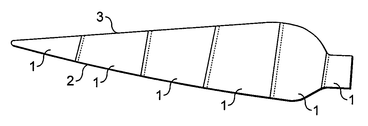
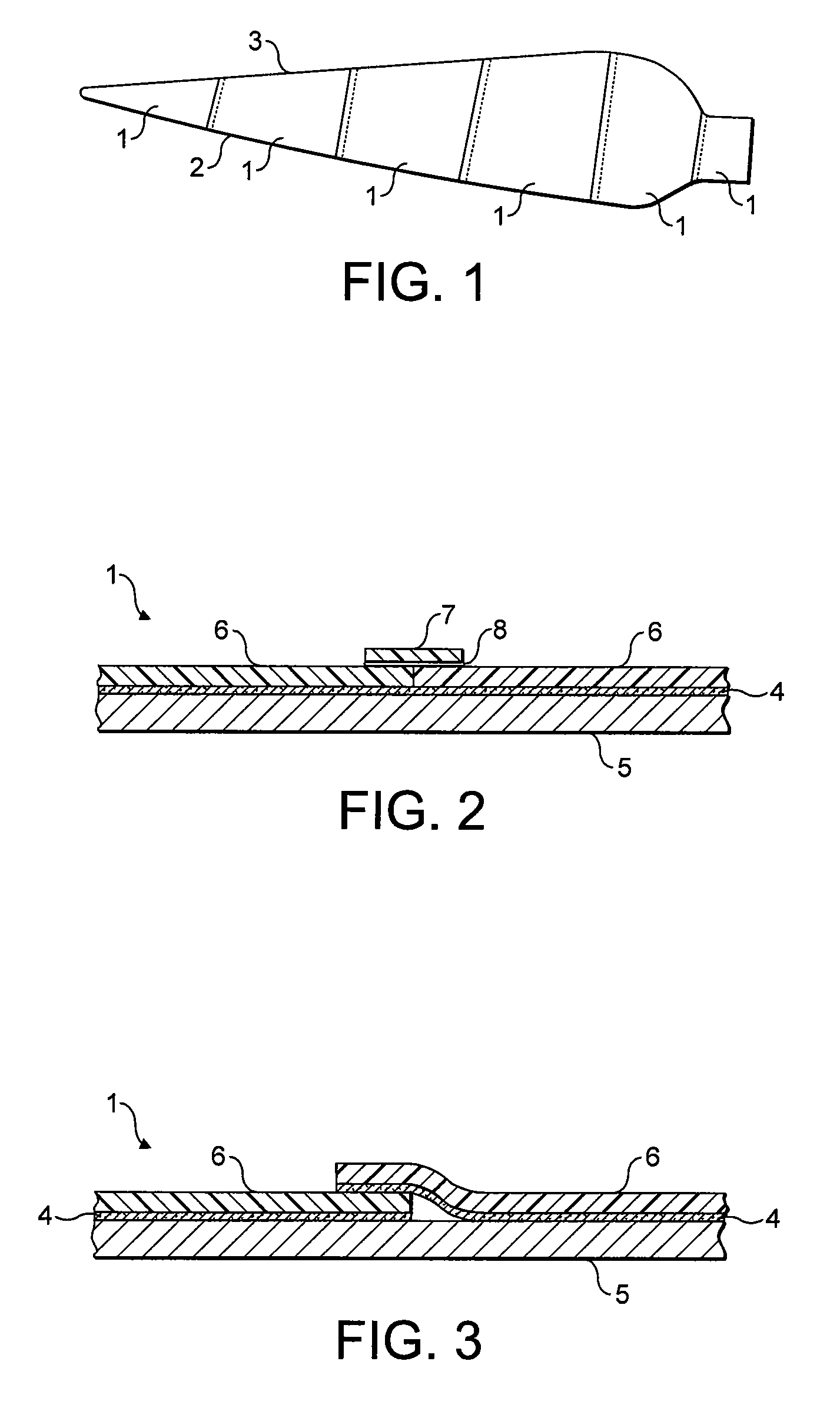
[0048]A wind turbine blade is shown in FIG. 1. The basic body of the blade may be formed in accordance with conventional techniques in which full length mouldings of each half are made and the two halves are joined together in a clam shell-like construction. Alternatively, the blades may have a modular construction as described in our earlier GB application number 0717690.2.

[0049]The present invention is concerned only with the surface coating. As can be seen from FIG. 1, the blade is covered with a number of strips 1 of self-adhesive of thermoplastic material 6 and adhesive 4. Each strip extends from the leading edge 2 to the trailing edge 3. The opposite side of the blade corresponds to this. At these leading and trailing edges 2, 3 the strip on one side may overlap slightly with the strip on the opposite side or a further thin strip may be provided along the edge to cover the join between strips in a similar manner to that described in the reference to FIGS. 2 and 3 below.

[0050]A...


PUM

PropertyMeasurementUnit
Fractionaaaaaaaaaa
Fractionaaaaaaaaaa
Fractionaaaaaaaaaa

Abstract

There is provided a wind turbine blade at least 50% of the surface of which is covered with a self-adhesive thermoplastic film. By applying a self-adhesive thermoplastic film to the blade, the need for a gelcoat or the paint is eliminated. It is estimated that the thermoplastic film will take a similar time to apply as the gelcoat and / or paint. However, it does not require any further treatment once it has been applied thereby reducing significantly the work involved in finishing the blade. Also, the thickness of the film is precisely controlled in advance of its application to the blade ensuring that a surface with a uniform thickness is produced.

Description

CROSS-REFERENCE TO RELATED APPLICATIONS[0001]This application claims benefit of Great Britain patent application serial number 0805713.5, filed Mar. 28, 2008, which is herein incorporated by reference.BACKGROUND OF THE INVENTION[0002]1. Field of the Invention[0003]The present invention relates to a wind turbine blade, and more specifically, to an improved surface coating for a wind turbine blade.[0004]The coating on the surface of a wind turbine blade is exposed to a harsh environment of abrasion, UV, humidity, corrosion, cyclical stresses, and extreme temperature fluctuation and requires a high performance material. Coatings need to retain performance for up to 20 years, putting them in a higher performance and different specification bracket than most civil / automotive applications and additionally be of a cost significantly lower than products typically found in aerospace applications.[0005]2. Description of the Related Art[0006]Wind turbine blades are typically coated using eithe...

Claims


Application Information

Patent Timeline
IPC IPC(8): B63H1/26
CPCB32B27/28B32B27/30Y10T29/49336Y02E10/721Y10T428/24942F03D1/065B32B27/08B32B27/18B32B27/20B32B27/304B32B27/308B32B27/322B32B27/40B32B2264/102B32B2270/00B32B2307/41B32B2307/514B32B2307/536B32B2307/558B32B2307/58B32B2307/712B32B2307/72B32B2307/724B32B2307/726B32B2603/00Y02E10/72Y02P70/50
Inventor RUDLING, PAUL
Owner BLADE DYNAMICS LTD
Learn More