Al technical title is built by PatSnap Al team. It summarizes the technical point description of the patent document.
a thin film and fabrication method technology, applied in plasma technology, vacuum evaporation coating, transportation and packaging, etc., can solve the problems of laser ablation and gradual breakdown of particle siz
Inactive Publication Date: 2009-10-01
IMRA AMERICA
View PDF39 Cites 44 Cited by
Summary
Abstract
Description
Claims
Application Information
AI Technical Summary
This helps you quickly interpret patents by identifying the three key elements:
Problems solved by technology
Method used
Benefits of technology
[0011]Experiments showed that by adjusting the time separation between the pulses within each burst, the ablation plume produced by a leading laser pulse can be modified by the subsequent pulses when the separation between pulses is short enough. Although it is not necessary to the practice of embodiments of the present invention to understand the operative mechanism therein, it appears the effect first builds up the charge density in the plume plasma, such that the plasma can block (i.e., absorb and reflect) the rest of the incoming pulses by the plasma shielding effect. This results in laser ablation of the nanoparticles contained in the plume and gradually breaks down the size of the particles.
[0012]In one aspect an ultrashort PLD process is pro...
Problems solved by technology
This results in laser ablation of the nanoparticles containe...
Method used
Image
Click on the blue label to locate the original text in one second.
Reading with bidirectional positioning of images and text.
Examples
Embodiment Construction
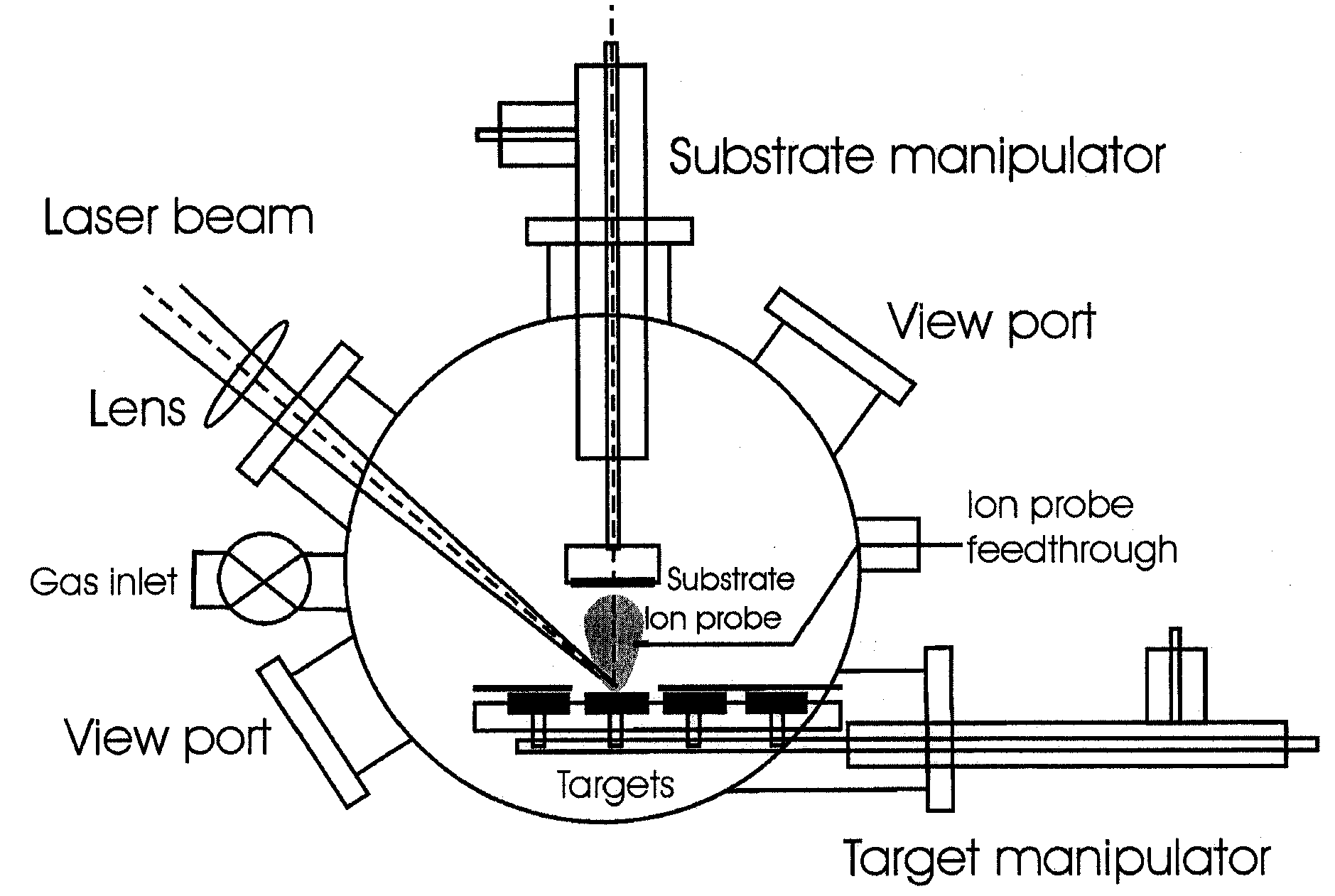
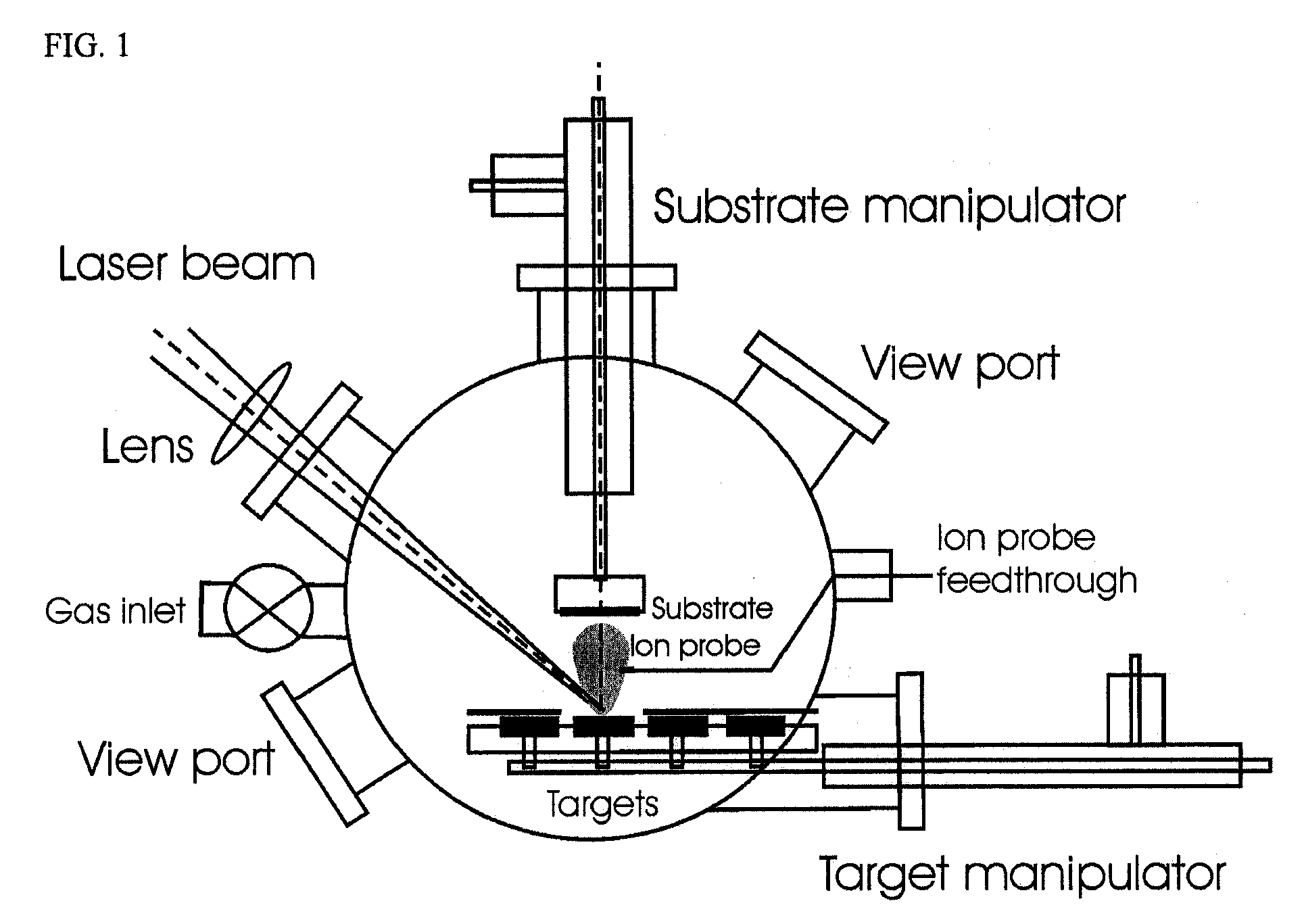
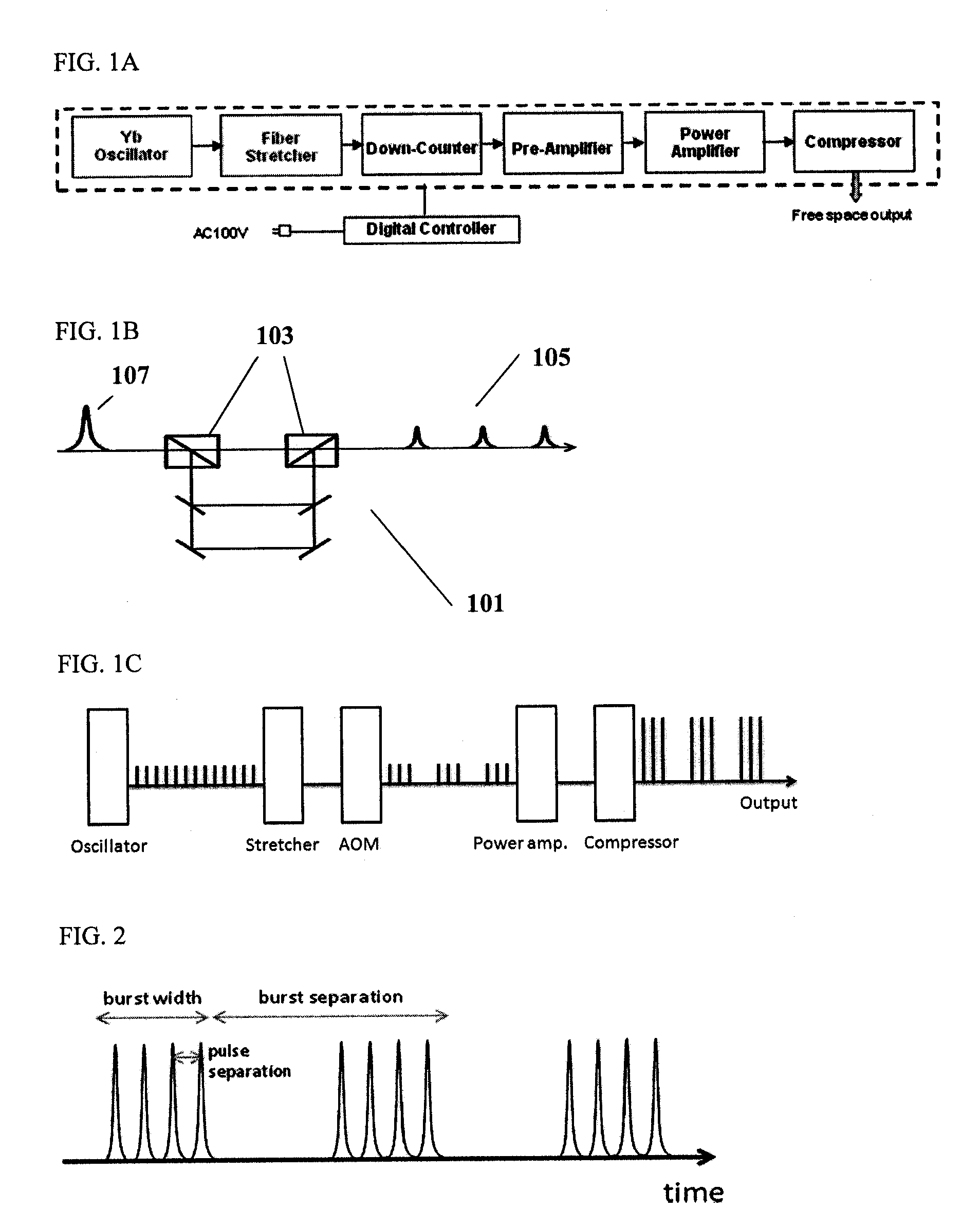
[0052]Embodiments of the present PLD invention generally utilize a burst of pulses for material synthesis to tune or otherwise control material morphology. For example, one or more laser pulses may be used to fabricate thin films so as to form distributions of nanoparticles with single ultrashort pulses. Additional pulses of a burst may be utilized to fabricate smooth, nearly particle free-films. Burst parameters, or parameters of pulses within a burst, may be based on known target emission characteristics. For example, a burst width of tens of nanoseconds, hundreds of nanoseconds, and up to several microseconds may be utilized in combination with pulses having a pulse width in a range of about 50 fs to about 100 ps. Generally a first pulse at least initiates a laser interaction with a target material, and at least a second pulse interacts with a by-product of the interaction. The interaction may be laser ablation and the by-product may include plume comprising charged and neutral p...
PUM
Property
Measurement
Unit
Time
aaaaa
aaaaa
Time
aaaaa
aaaaa
Time
aaaaa
aaaaa
Abstract
A method of pulsed laser deposition (PLD) capable of continuously tuning formed-film morphology from that of a nanoparticle aggregate to a smooth thin film free of particles and droplets. The materials that can be synthesized using various embodiments of the invention include, but are not limited to, metals, alloys, metal oxides, and semiconductors. In various embodiments a ‘burst’ mode of ultrashort pulsed laser ablation and deposition is provided. Tuning of the film morphology is achieved by controlling the burst-mode parameters such as the number of pulses and the time-spacing between the pulses within each burst, the burst repetition rate, and the laser fluence. The system includes an ultrashort pulsed laser, an optical system for delivering a focused onto the target surface with an appropriate energy density, and a vacuum chamber in which the target and the substrate are installed and background gases and their pressures are appropriately adjusted.
Description
CROSS REFERENCE TO RELATED APPLICATIONS [0001]This application claims priority to Application No. 61 / 039,883, entitled “A Method for Fabricating Thin Films”, filed Mar. 27, 2008. This application claims priority to application Ser. No. 12 / 254,076, entitled “A Method for Fabricating Thin Films”, filed Oct. 20, 2008, which claims priority to Application No. 61 / 039,883, entitled “A Method for Fabricating Thin Films”, filed Mar. 27, 2008. This application is also related to application Ser. No. 11 / 798,114, entitled “Method for Depositing Crystalline Titania Nanoparticles and Films”, filed May 10, 2007, now published as U.S. Patent Application Pub. No. 2008 / 0187864, and assigned to the assignee of the present invention. The disclosures of application numbers 61 / 039,883 and Ser. Nos. 11 / 798,114 and 12 / 254,076, are hereby incorporated by reference in their entirety.FIELD OF THE INVENTION [0002]This invention is related to pulsed laser deposition (PLD) using a pulsed laser to fabricate thin...
Claims
Application Information
Patent Timeline
Application Date:The date an application was filed.
Publication Date:The date a patent or application was officially published.
First Publication Date:The earliest publication date of a patent with the same application number.
Issue Date:Publication date of the patent grant document.
PCT Entry Date:The Entry date of PCT National Phase.
Estimated Expiry Date:The statutory expiry date of a patent right according to the Patent Law, and it is the longest term of protection that the patent right can achieve without the termination of the patent right due to other reasons(Term extension factor has been taken into account ).
Invalid Date:Actual expiry date is based on effective date or publication date of legal transaction data of invalid patent.