[0004]The ultrasonic welding device of the invention having the characteristics of claim 1 has the
advantage over the prior art that with its simpler construction and its ability to be produced at a lower cost, a constant width of a working gap can be assured. As a result, a very good welding quality can be obtained. In particular, by means of the ultrasonic welding device of the invention, not only plastic films but
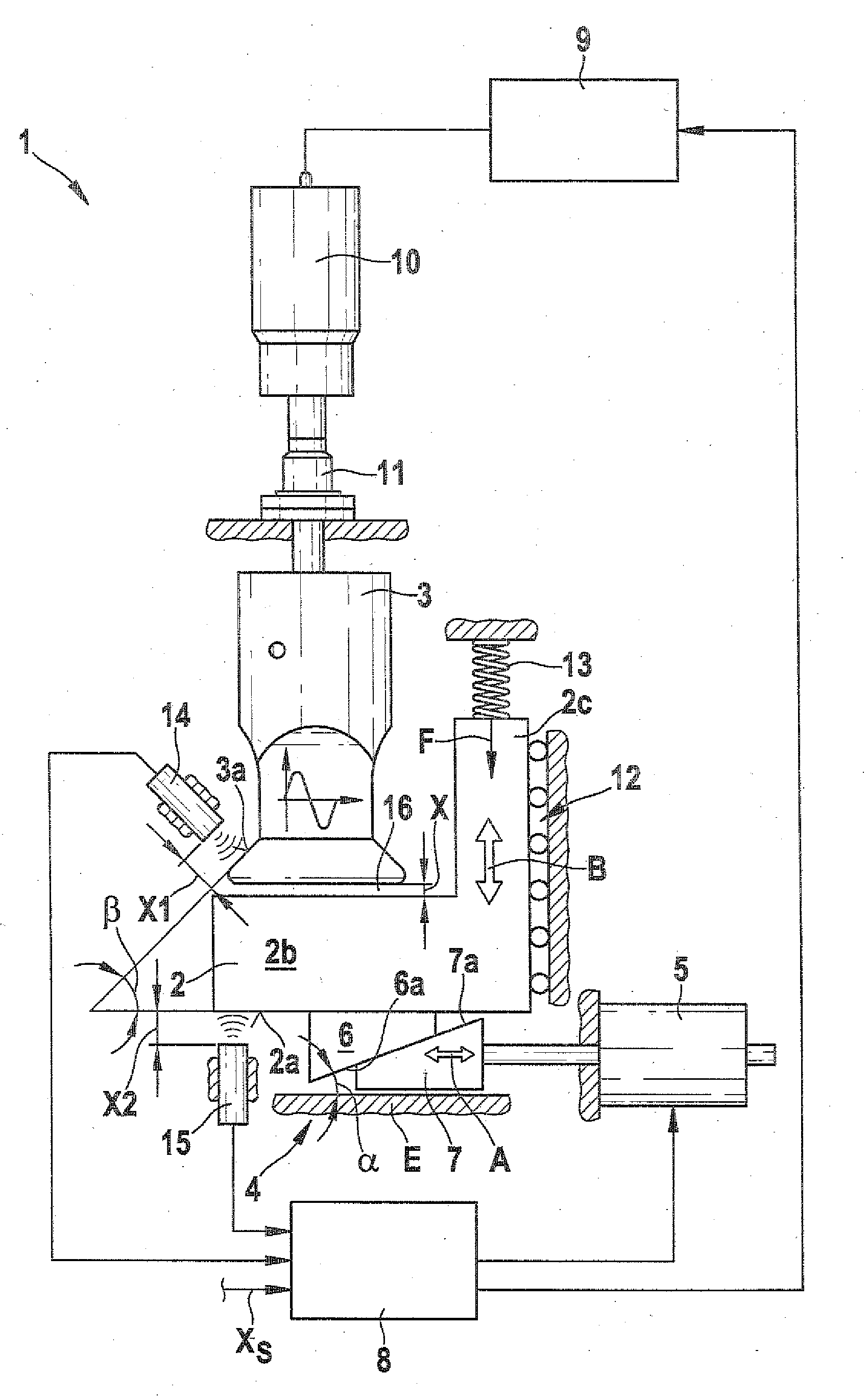
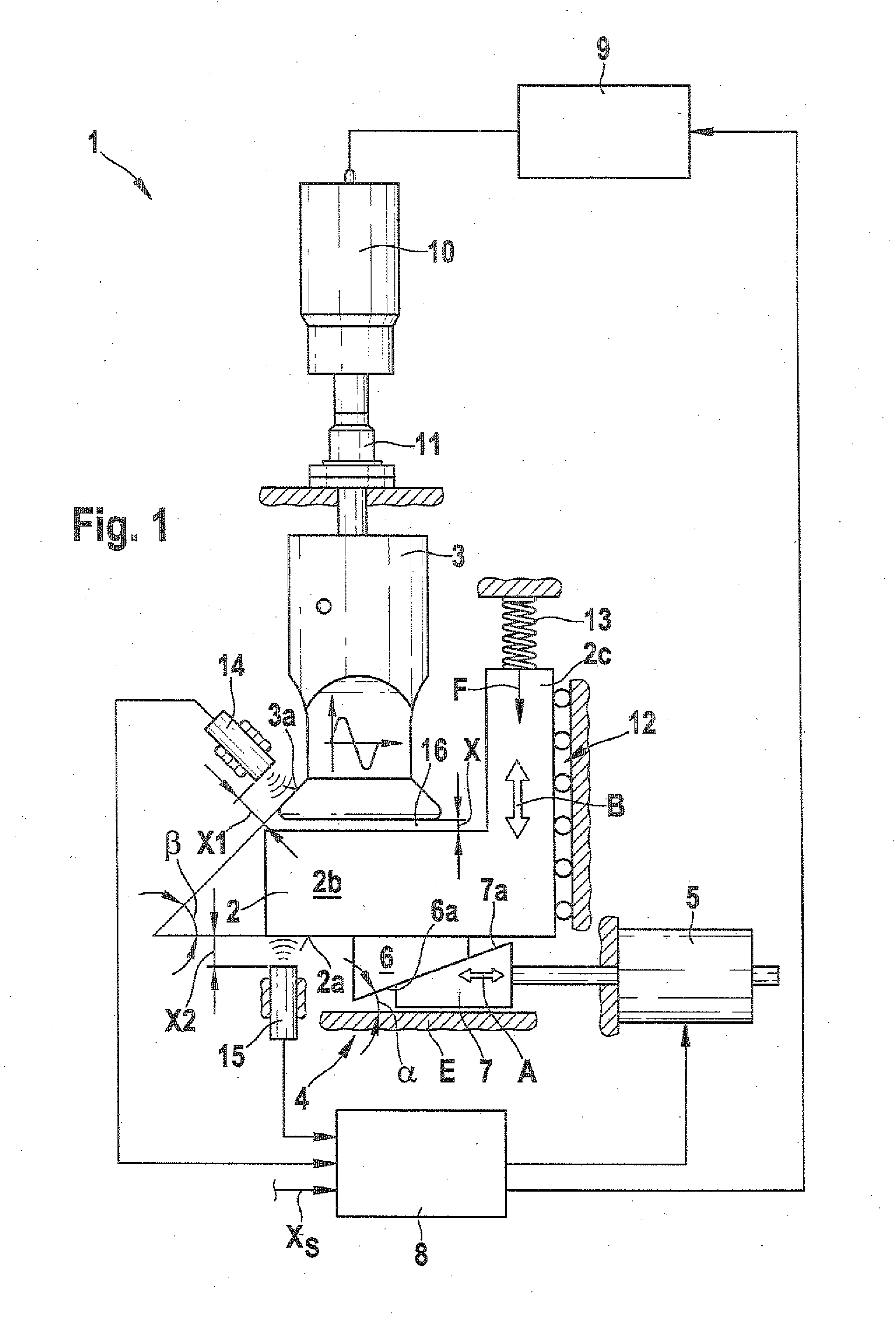
metal-coated films, for instance for packaging foods, can be safely welded. This is attained according to the invention in that the ultrasonic welding device includes an ultrasonic sonotrode, an anvil, an adjusting device for adjusting a relative position between the ultrasonic sonotrode and the anvil; and a regulating device for regulating a width of a working gap. The adjusting device has a first wedge element, connected to the anvil, and a second wedge element connected to an
actuator. By a
relative motion of the second wedge element to the first wedge element, a motion of the anvil in the direction of the
gap width can be attained, so that, monitored by the regulating device, a constant width of the working gap can be assured. The ultrasonic welding device of the invention is especially simply and sturdily constructed. By the use of two wedge elements, very precise regulation of the gap widths can also be accomplished.
[0011]The actuator of the adjusting device is preferably a
linear actuator. As a result, the actuator can be constructed very simply and inexpensively, for instance as a
piston-cylinder unit.
[0011]The actuator of the adjusting device is preferably a
linear actuator. As a result, the actuator can be constructed very simply and inexpensively, for instance as a
piston-cylinder unit.
[0011]The actuator of the adjusting device is preferably a
linear actuator. As a result, the actuator can be constructed very simply and inexpensively, for instance as a
piston-cylinder unit.
[0009]For regulating the width of the working gap, the regulating device preferably actuates the actuator and / or regulates a supply of
electrical current to the ultrasonic sonotrode.
[0009]For regulating the width of the working gap, the regulating device preferably actuates the actuator and / or regulates a supply of
electrical current to the ultrasonic sonotrode.
[0008]Also preferably, the ultrasonic welding device includes a first spacing sensor and a second spacing sensor. The two spacing sensors are each disposed in stationary fashion. The first spacing sensor determines a first spacing between the first spacing sensor and the ultrasonic sonotrode, and the second spacing sensor determines a second spacing between the second spacing sensor and the anvil. The regulating device calculates the actual width of the working gap based on the first and second spacings.
[0011]The actuator of the adjusting device is preferably a linear actuator. As a result, the actuator can be constructed very simply and inexpensively, for instance as a piston-cylinder unit.
[0012]Also preferably, a sloping plane of the first wedge element and a sloping plane of the second wedge element are disposed at an angle of between 1° and 10°, preferably between 3° and 7°, to a
base plane. As a result, it can be assured that by means of an only very short
stroke, a relatively major change in the width of the working gap can be established.
[0013]The invention further relates to a
packaging machine, in particular a bag
package-making
machine, including an ultrasonic welding device in accordance with the present invention. The ultrasonic welding device here is used in particular for welding longitudinal and / or transverse seams of bag packages.
[0014]It should be noted that the ultrasonic welding device of the invention can be used not only for welding identical materials but also for welding different materials, such as a
plastic film and a
metal-coated film.

