

Carbon nanotube composition, method for manufacturing the same, array, and electronic device
a technology of carbon nanotubes and carbon nanotubes, applied in nanoinformatics, natural mineral layered products, synthetic resin layered products, etc., can solve the problems of certain number of swnts being structure, and the effect of not being achieved
- Summary
- Abstract
- Description
- Claims
- Application Information
AI Technical Summary
Benefits of technology
Problems solved by technology
Method used
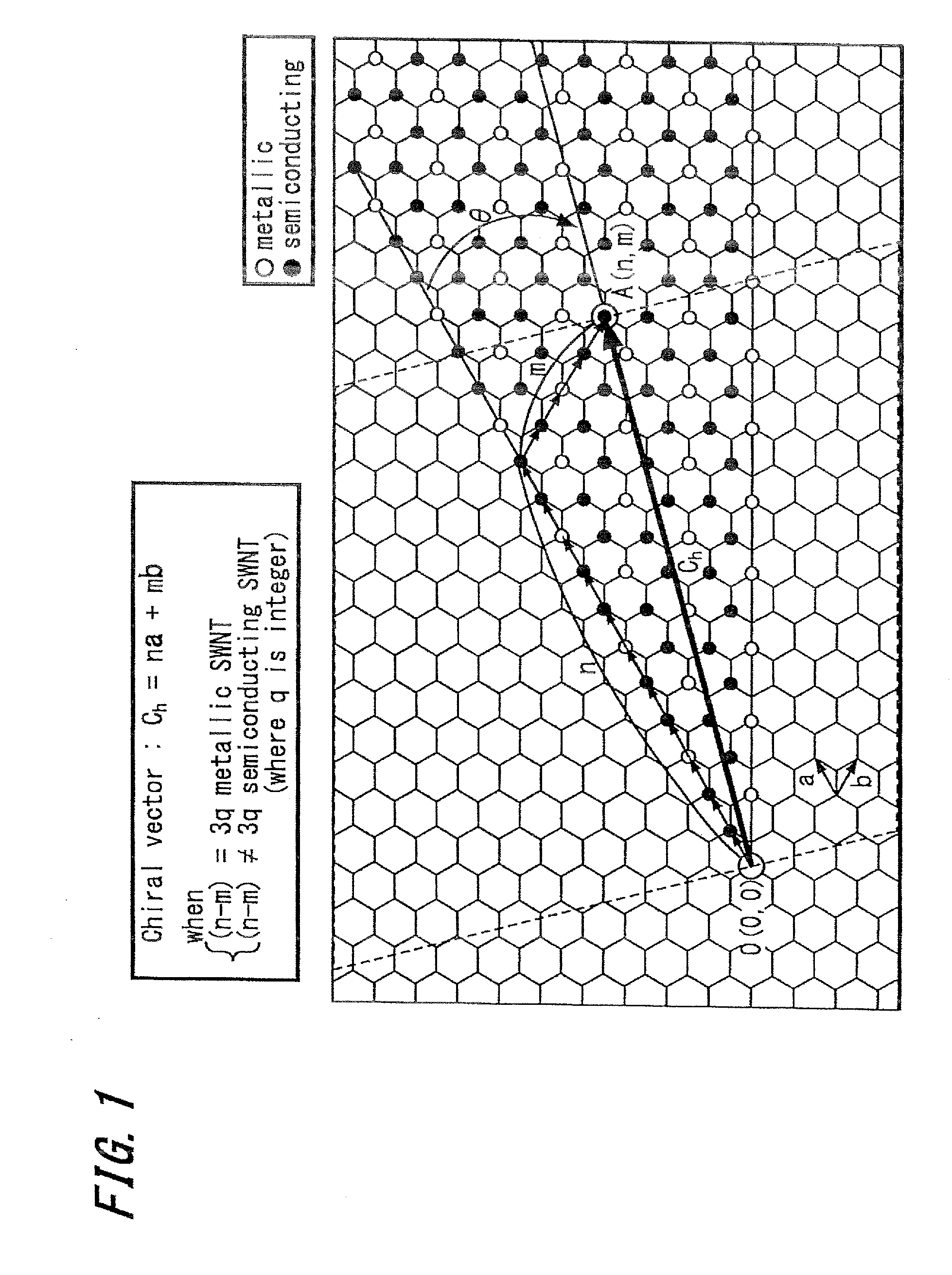
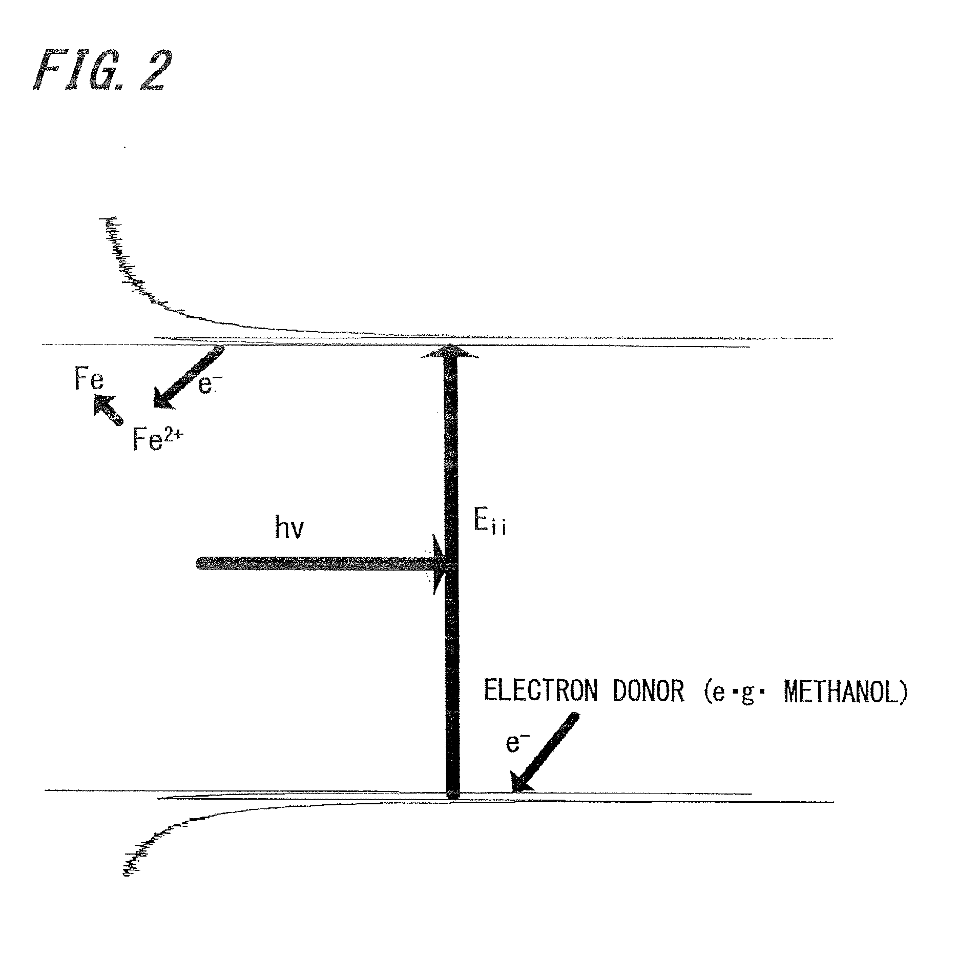
Image

Examples
example 1
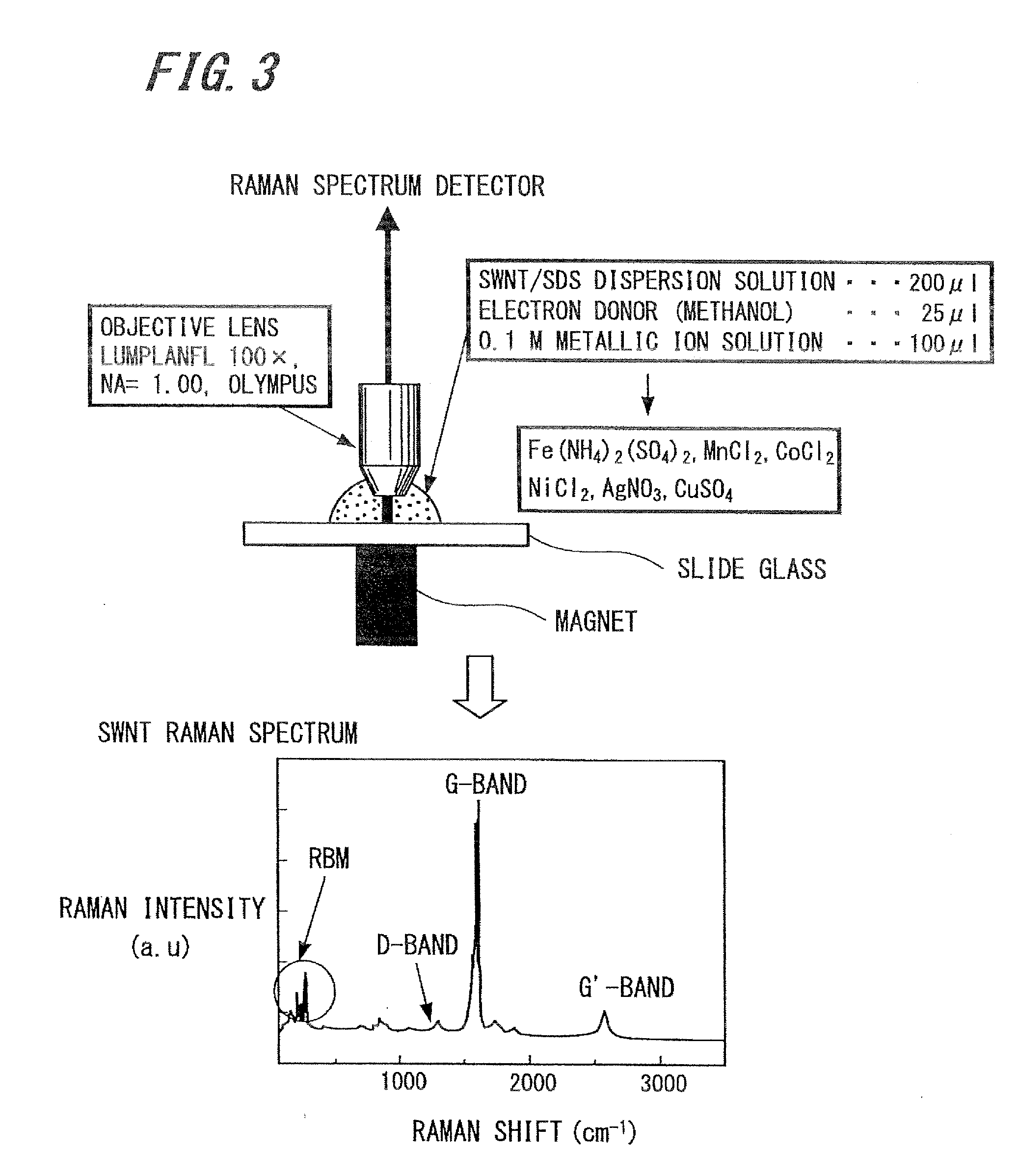
Immobilization of SWNTs and Raman Analysis
[0158]The commercially available SWNT produced by the HiPco method, which is one kind of CVD methods, was mixed with 1 wt % of dodecylsodium sulfate (SDS) solution, irradiated with ultrasonic wave in an ultrasonic bath for one hour, and then centrifuged at 14,000 rpm for one hour to separate a supernatant fluid, that is, a SWNT / SDS dispersion. 200 μL of the SWNT / SDS dispersion (SWNT: about 10 μg / mL) was mixed with methanol to have a methanol concentration of 2 M and spotted at two positions separately on a glass substrate. One spot was supplied with an aqueous ferrous sulfate ammonium sulfuric acid solution to get a pH of about 3 and a Fe (II) ion concentration of 10 mM. The other spot is supplied with an aqueous manganese chloride solution to get a pH of about 6 and a Mn (II) ion concentration of 10 mM. Next, both the spots were irradiated with laser beam having a wavelength of 785 nm which was converged by an optical lens to have a diamete...
example 2
Control of Amount of Fixed SWNTs
[0165]The commercially available SWNTs produced by the HiPco method, which is one kind of CVD methods, were mixed with 1 wt % of dodecylsodium sulfate (SDS) solution, irradiated with ultrasonic wave in an ultrasonic bath for one hour, and then centrifuged at 14,000 rpm for one hour to separate a supernatant fluid, that is, an SWNT / SDS dispersion. 200 μL of the SWNT / SDS dispersion (SWNT: about 10 μg / mL) was mixed with methanol to have a methanol concentration of 2 M and kept on a glass substrate. This resultant was supplied with an aqueous ferrous sulfate ammonium sulfuric acid solution to get a pH of about 3 and a Fe (II) ion concentration of 10 mM, and then irradiated with laser beam having a wavelength of 785 nm which was converged by an optical lens to have a diameter of about 1 μm A rare earth permanent magnet (magnetic flux density: about 60 mT) was placed immediately under the substrate at photo irradiated spot to apply a magnetic field.
[0166]Th...
example 3
Fabrication of SWNT Array
[0169]The position of light-irradiated spot can be controlled to fabricate and pattern a SWNT array.
[0170]The optical microscopic image of a SWNT microdot array formed on a glass substrate with laser beam having a wavelength of 785 nm which was converged to have a diameter of about 1 μm is shown in FIG. 8.
[0171]As known from FIG. 8, the positions at which to immobilize SWNTs could be controlled in a micrometer order (in the same condition of 100% T with a magnetic field applied as in FIG. 7).
[0172]The excitation light was scanned on the substrate to immobilize continuously and optically pattern the SWNTs. Moreover, the wavelength of the excitation light could be changed to form films for conjugating the SWNTs having different band gaps could be formed.
PUM
| Property | Measurement | Unit |
|---|---|---|
| wavenumber | aaaaa | aaaaa |
| wavenumber | aaaaa | aaaaa |
| diameter | aaaaa | aaaaa |
Abstract
Description
Claims
Application Information