Extendible stent apparatus

a stent and apparatus technology, applied in the field of intravascular stents, can solve the problems of inconvenient and costly use, inconvenient and costly, and insufficient attachment or coating of a substance or drug on the coronary stent, and achieve the effect of increasing the amount of coating substan

Inactive Publication Date: 2009-10-08
BOSTON SCI SCIMED INC
View PDF68 Cites 11 Cited by
  • Summary
  • Abstract
  • Description
  • Claims
  • Application Information

AI Technical Summary

Benefits of technology

[0014]Accordingly, an object of the present invention is to provide an intravascular stent with a geometry that provides for an increased amount of a coating substance.

Problems solved by technology

Although the brachytherapy (radiation treatment) has proved to be reasonably effective in further reducing restenosis after stent implant, using brachytherpy is very cumbersome, inconvenient and costly.
The laser and atherectomy devices proved to be marginally useful in this purpose with added costs.
However, attaching or coating a sufficient amount of a substance or drug on the coronary stent is not so easy a proposition.
Coating a drug or an agent on the surface of the stent has a demanding problem of enough volume of such substance coated on the small surface areas of stent struts, without increasing the physical width or thickness of stent struts.
This demand directly conflicts with the metal fraction issue of the stent.
This means that drug coating is a very demanding task.
An average stent, particularly a coronary stent, will have problem of providing desired amount of drug-retaining capacity on the surface areas of the stent struts.

Method used


Image

  • Extendible stent apparatus
  • Extendible stent apparatus
  • Extendible stent apparatus

Examples


Embodiment Construction

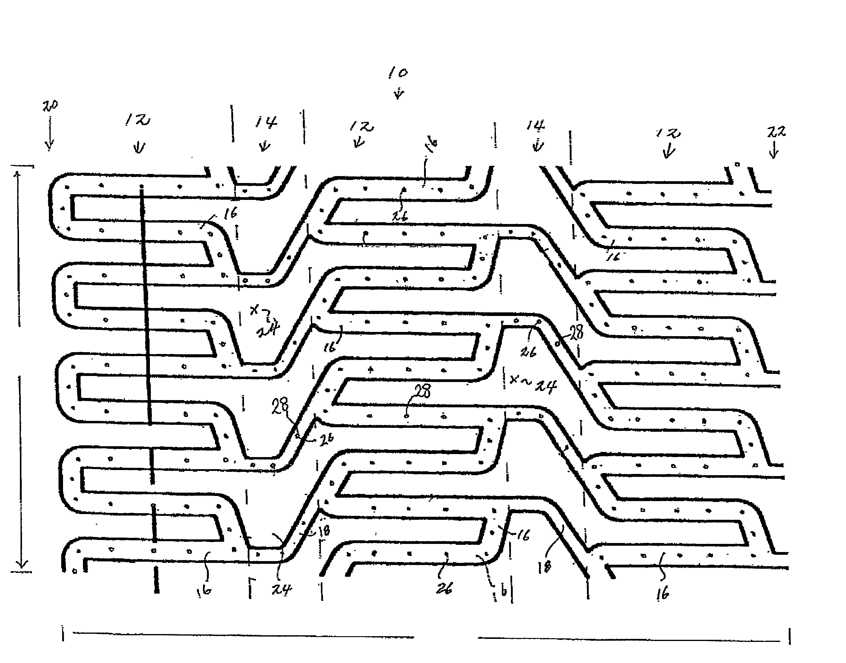
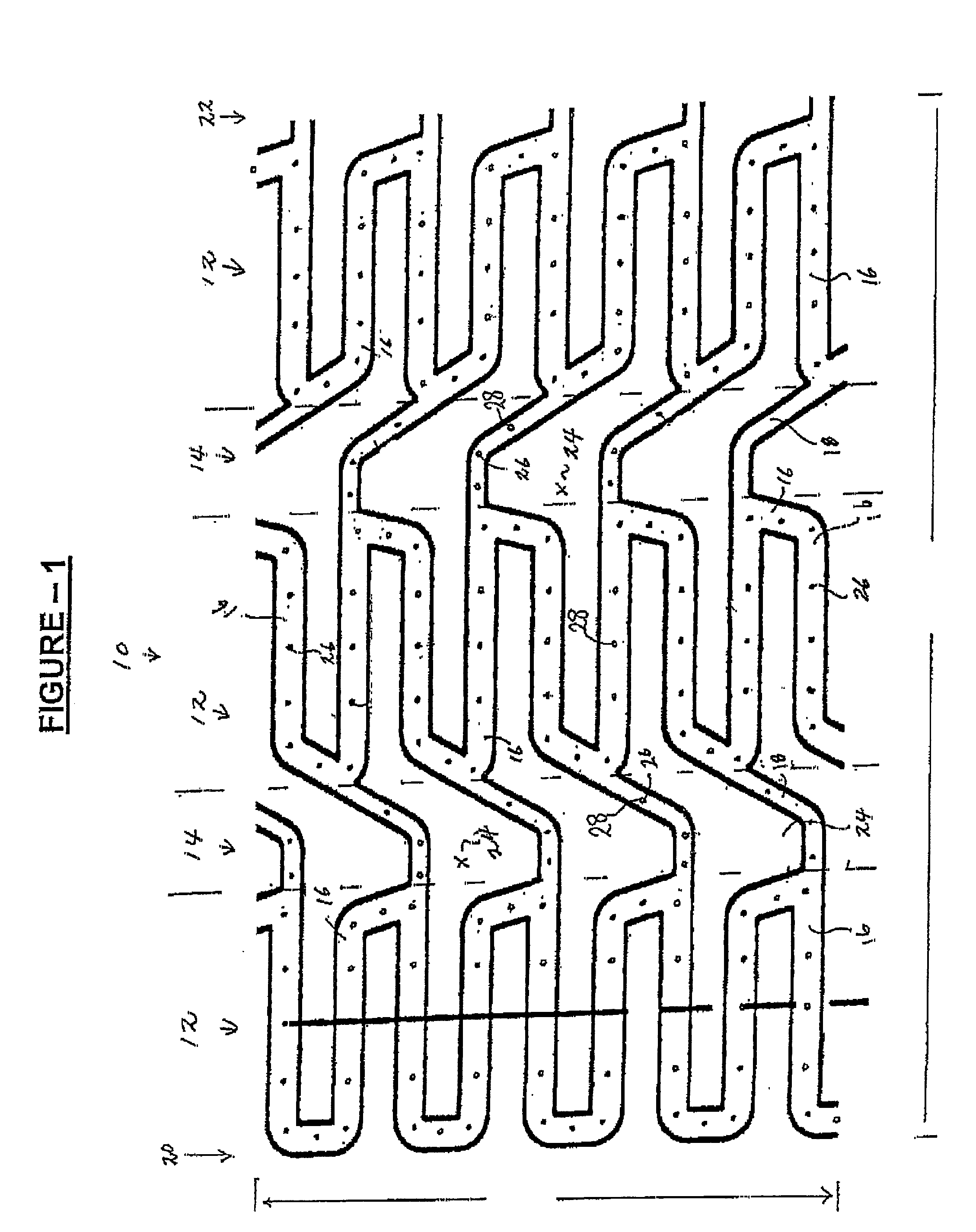
[0032]Referring now to FIG. 1, one embodiment of an expandable stent 10 of the present invention is illustrated. A tubular structure includes an outer surface positionable adjacent to a vessel wall and an inner surface facing a lumen of a body passageway. The tubular structure further includes a plurality of expansion struts, connector struts and cells. The tubular structure has a first diameter which permits intraluminal delivery of the tubular structure into the body passageway, and a second expanded and deformed diameter which is achieved upon the application of a radially, outwardly extending force.

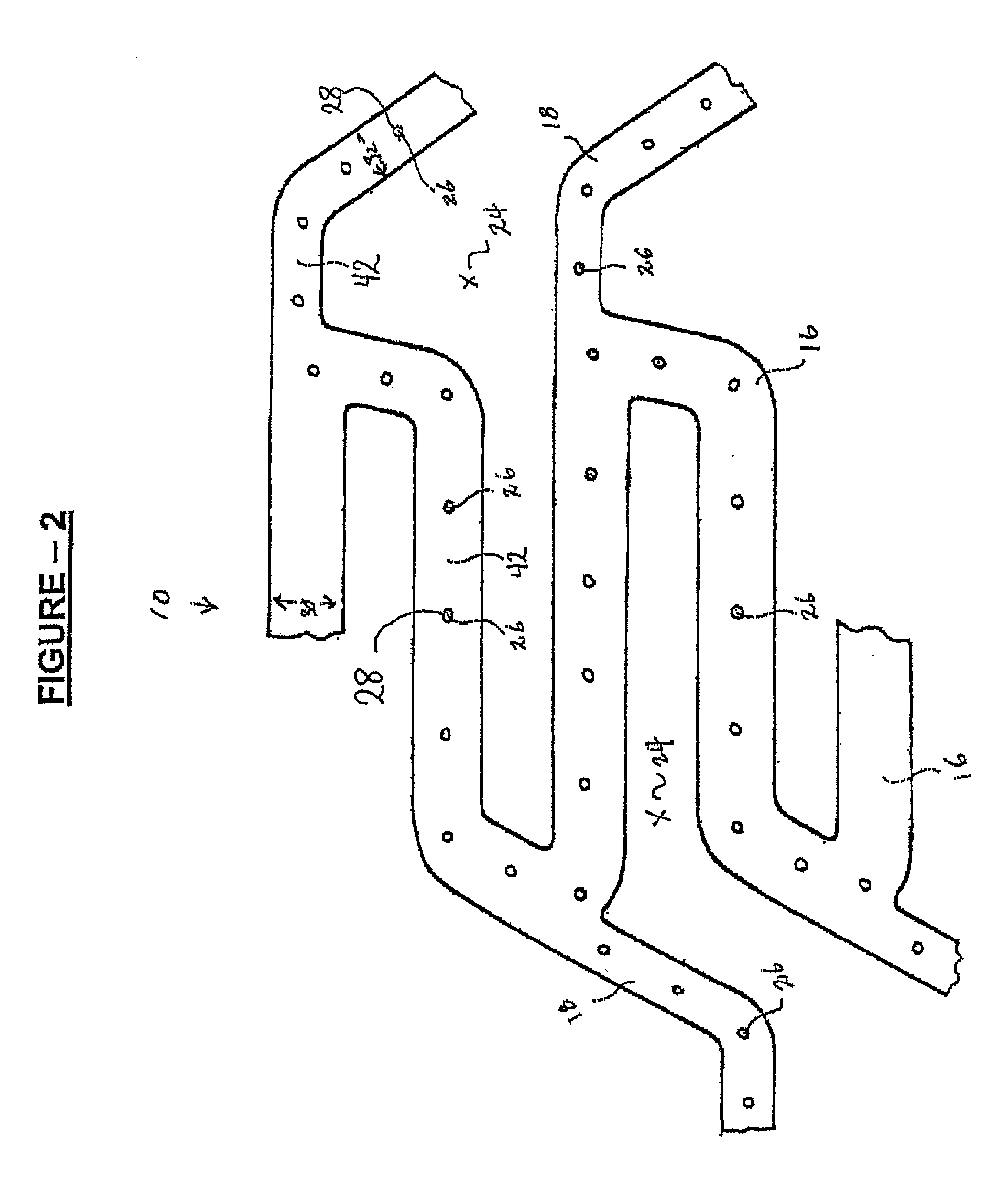
[0033]A plurality of cavities are formed in the outer surface of the stent. The cavities can be micro-holes or micro-slits and extend from the outer surface to an interior of the struts, or extend from the outer surface all the way through the inner surface. An example of a stent design useful with the present invention is disclosed in U.S. Pat. No. 5,954,743, incorporated herein by r...


PUM


Abstract

An expandable stent includes a tubular structure with an outer surface positionable adjacent to a vessel wall and an inner surface facing a lumen of a body passageway. The tubular structure further includes a plurality of expansion struts, connector struts and cells. The tubular structure has a first diameter which permits intraluminal delivery of the tubular structure into the body passageway, and a second expanded and deformed diameter which is achieved upon the application of a radially, outwardly extending force. A plurality of cavities are formed in the outer surface of the stent.

Description

CROSS-REFERENCE TO RELATED APPLICATIONS[0001]This Application is a continuation of application Ser. No. 10 / 297,372, filed Jul. 18, 2003, which is a National Stage Entry of PCT / US01 / 18419, filed Jun. 5, 2001, which claims priority to U.S. Provisional Application No. 60 / 209255 filed Jun. 5, 2000.STATEMENT REGARDING FEDERALLY SPONSORED RESEARCH[0002]Not ApplicableBACKGROUND OF THE INVENTION[0003]1. Field of Invention[0004]This invention relates generally to intravascular stents, and more particularly to intravascular stents that include a plurality of cavities formed on a surface of the stent and are coated with a restenosis inhibiting agent.[0005]2. Description of the Related Art[0006]By 1999, the percutaneous balloon angioplasty and stent implant procedures have become the dominant non-surgical revascularization method of the atherosclerotic stenosis, or obstruction, of the vascular lumen, and particularly in the coronary vascular system in the heart. With balloon angioplasty alone, ...

Claims


Application Information

Patent Timeline
Patent Type & Authority Applications(United States)
IPC IPC(8): A61F2/06A61F2/84A61F2/00A61F2/82A61F2/90
CPCA61F2/91A61F2/915A61F2250/0068A61F2002/91533A61F2002/91558A61F2002/91525
Inventor JANG, G. DAVID
Owner BOSTON SCI SCIMED INC
Why Eureka
Try Eureka