
Digital camera sensor cleaning and lense changing case

a digital camera and lense technology, applied in the direction of photosensitive materials, instruments, packaged goods, etc., can solve the problems of affecting digital images, image sensors are very susceptible, and new set of problems, and achieve the effect of high luminosity

Inactive Publication Date: 2009-10-15
BEITMAN RICHARD CLARK HOWELL
View PDF15 Cites 6 Cited by
  • Summary
  • Abstract
  • Description
  • Claims
  • Application Information

AI Technical Summary

Benefits of technology

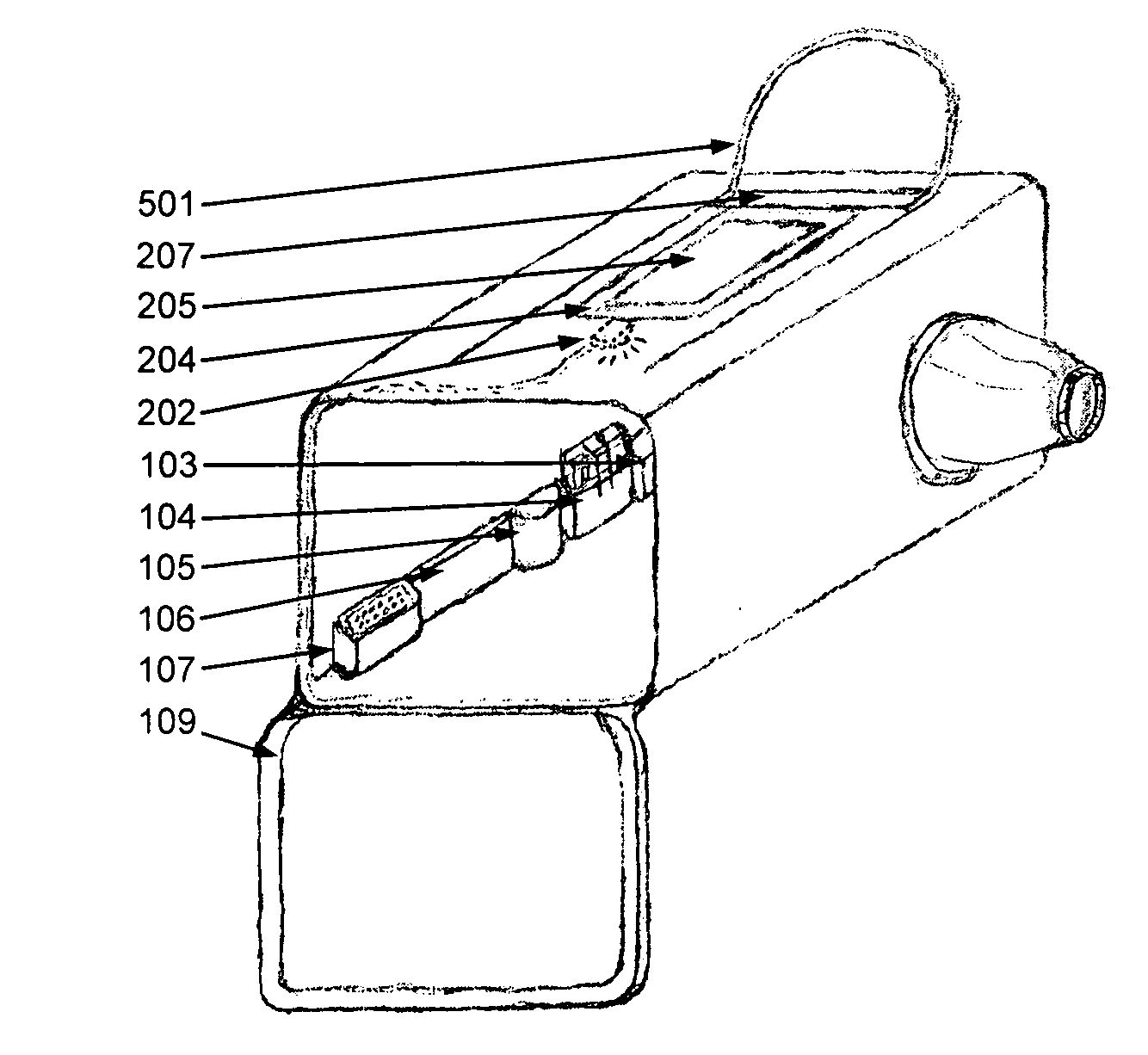
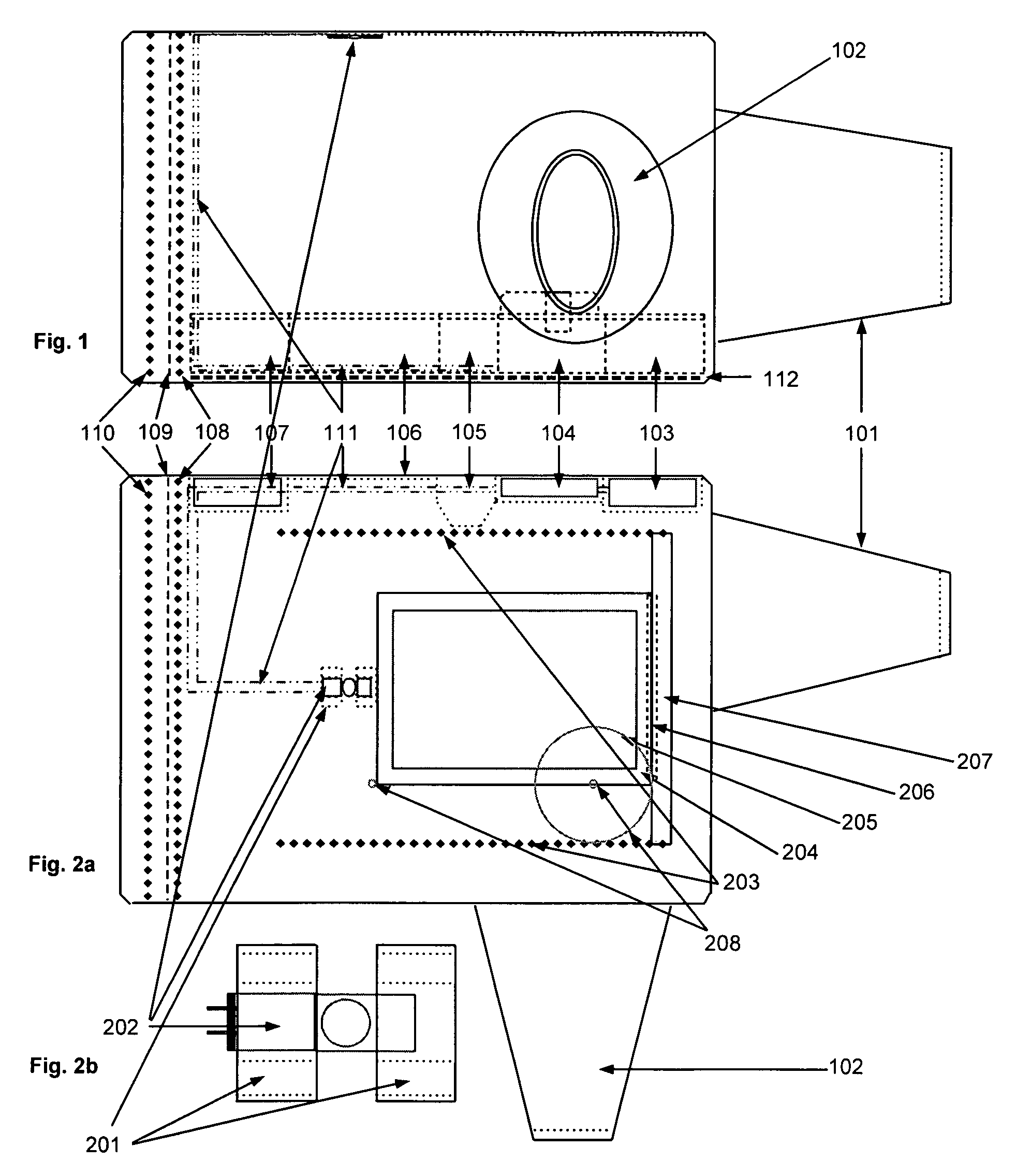
[0002]It is an object of the present invention to provide a method and mobile environmental chamber for the operator of a digital SLR camera, digital rangefinder camera, digital medium format camera, and medium and large format digital camera backs to change lenses and / or expose the internal cavity of the camera or sensor area whereby creating a very low particle environment as a prophylaxis to particle contamination of the sensor that would impair images or require more frequent cleaning of the sensor as is currently the standard mode of operation. During photographic operations, a camera with a lens, and an additional lens to be changed to can be secured inside the case via a dual-zippered quick entrance upper panel. Turning on the power pack energizes both a tuned complimentary Ion generator that scrubs the air of microscopic particles and suppresses static charge, and energizes a high luminosity wide beam solid state overhead light. Inserting hands and forearms through two tapered arm sleeves with elastic seals enables the operator to change the lenses without introducing new particulates. The primary case compartment was designed to accommodate changing lenses in the most common focal lengths up to 400 mm. An extension compartment concealed in the end panel can be deployed to support optics up to 800 mm.
[0003]It is an object of the present invention to provide a method and chambered environment for the operator of a digital SLR camera, digital rangefinder camera, digital medium format camera, and medium and large format digital back to clean a contaminated sensor in a low particle environment to reduce the risk of particle contamination while the sensor is exposed as is currently the standard mode of operation. In the sensor cleaning operation, the same advantages as stated above apply. Additionally two other objects of the design are an interchangeable overhead Fresnel magnifier designed into the upper windowed panel and a high luminosity overhead light. These objects allow greater visibility for fine work, inspection, and low light operation. The side panels of the case have elastic utility pouches installed for storing and accessing sensor cleaning materials creating an efficient, uncluttered working environment while doing a sensor cleaning mirror up operation.
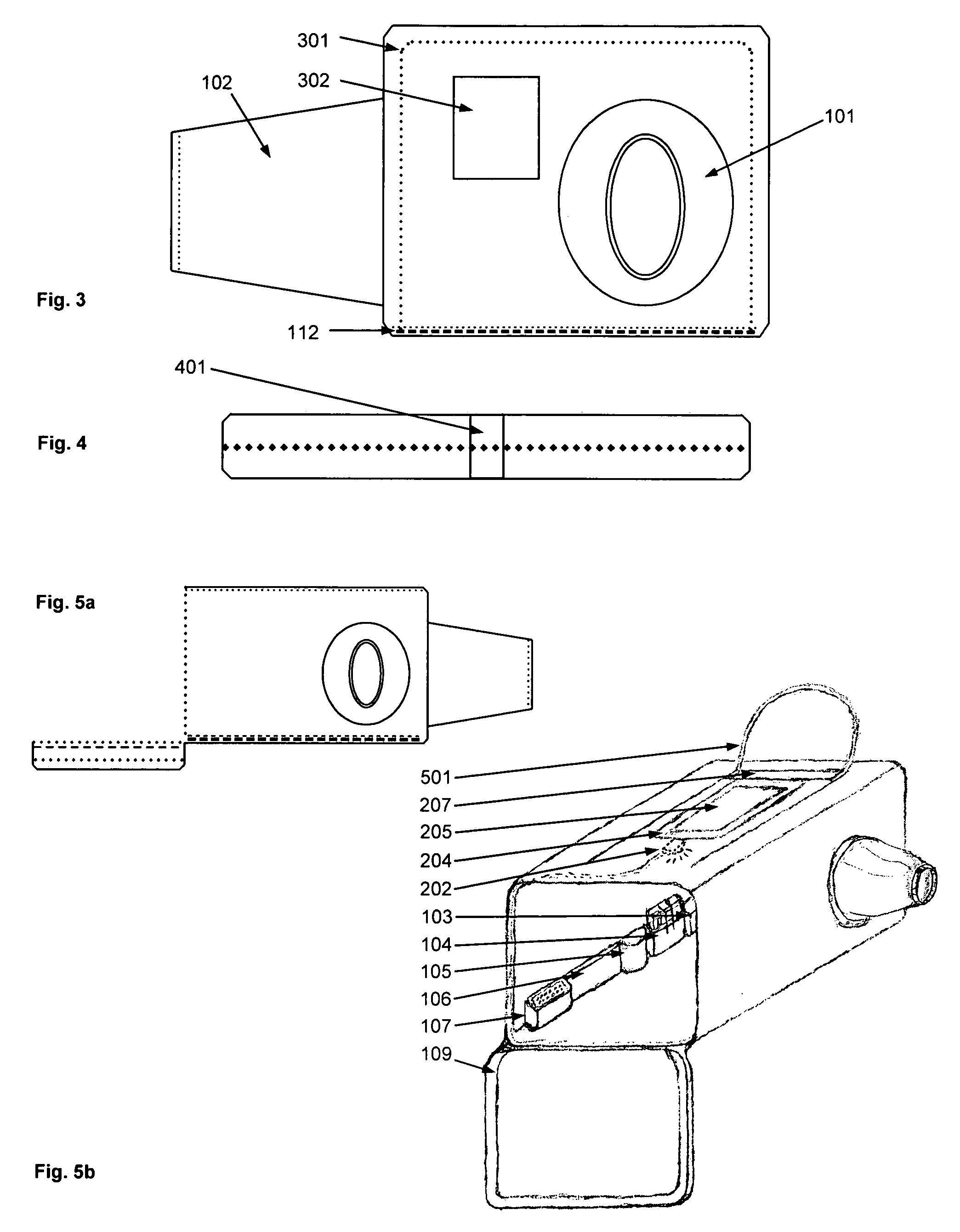
[0004]It is an object of the present invention to provide a method of photographing in the rain. The primary chamber is comprised of two layers of water resistant material. The end panel zips down creating a recessed aperture for the camera, minimizing the risk of water damage to the equipment and minimizing water obscuring the optics. A clear vinyl window is designed into the control end of the chamber enabling the operator to compose images in either portrait or landscape mode either through the viewfinder or LCD preview screen. This design also gives the operator freedom of not being tethered to a tripod.

Problems solved by technology

With the advent of the digital SLR (Single Lens Reflex) camera, digital rangefinder camera, digital medium format camera, and medium and large format digital camera backs replacing their film counterparts, a new set of problems have arisen.
The size and pitch of these pixels makes the image sensor very susceptible to microscopic dust particles that impair the digital images with artifacts.

Method used


Image

  • Digital camera sensor cleaning and lense changing case
  • Digital camera sensor cleaning and lense changing case
  • Digital camera sensor cleaning and lense changing case

Examples


Embodiment Construction

[0018]While the present invention will hereinafter be described in connection with various embodiments thereof, it will be understood that it is not intended to limit the invention to these embodiments. On the contrary, it is intended to cover all alternatives, modifications and equivalents that may be included within the spirit and scope of the invention as defined by the appended claims.

[0019]For a general understanding of the features of the present invention, reference is made to the drawings, like reference numerals have been used throughout to designate identical elements. FIG. 1 and FIG. 2a schematically depict the side and top view of the main chamber of the invention erect. The main chamber is comprised of two layers of water resistant fabric. The outer layer is of a heavier gauge then the inner lining. Various supple materials will be used comparable to a Poly Denier. The primary functions of the main chamber wall material are to create a wind block eliminating wind curren...


PUM

PropertyMeasurementUnit
Lengthaaaaaaaaaa
Lengthaaaaaaaaaa
Lengthaaaaaaaaaa

Abstract

Disclosed is a collapsible field deployable environmental enclosure device with internal electronic air scrubbing and static suppression electronics, high luminosity wide angle solid state lighting, magnifying optics, viewing ports, an expansion compartment, utility compartments, and sealed operator arm ports. This device was developed for the purpose of containing a Digital SLR (Single Lense Reflex) camera, a digital rangefinder camera, a digital medium format camera, or medium and large format digital camera backs. The stated equipment is contained within the invention as a prophylactic method of avoiding dust and particle contamination to the sensor and body cavity while in the process of exposing the internal body cavity and or the digital image sensor during the operations of either changing lenses, cleaning the image sensor, or other inspection and maintenance procedures. This invention may also be used for other particle sensitive equipment. The enclosure was also developed to facilitate photographing in rain conditions.

Description

BACKGROUND OF THE INVENTION[0001]With the advent of the digital SLR (Single Lens Reflex) camera, digital rangefinder camera, digital medium format camera, and medium and large format digital camera backs replacing their film counterparts, a new set of problems have arisen. The ultra high resolution digital image sensors that have replaced analog film are composed of millions to tens of millions of individual pixel sensors that comprise the overall picture image. These pixels vary in pitch based on the overall sensor density from approximately 3 to 9 microns in pitch. The size and pitch of these pixels makes the image sensor very susceptible to microscopic dust particles that impair the digital images with artifacts. The susceptibility of the sensor to dust particles transpires whenever a lens is removed from the camera body exposing the sensor cavity to ambient air. The sensor becoming contaminated with particles can also become exacerbated when particles that have entered the senso...

Claims


Application Information

Patent Timeline
IPC IPC(8): B65D85/38
CPCG03B17/56
Inventor BEITMAN, RICHARD CLARK HOWELL
Owner BEITMAN RICHARD CLARK HOWELL
Learn More