
Surface acoustic wave devices

a surface acoustic wave and waveguide technology, applied in piezoelectric/electrostrictive/magnetostrictive devices, piezoelectric/electrostriction/magnetostriction machines, electrical equipment, etc., can solve the problem of temperature change shift due to temperature change, the temperature characteristics of devices are hardly improved compared, and the temperature characteristics of devices are hardly improved, so as to improve the temperature characteristics and temperature coefficient of frequency , the effect of temperature coefficien

Active Publication Date: 2009-10-15
NGK INSULATORS LTD
View PDF10 Cites 9 Cited by
  • Summary
  • Abstract
  • Description
  • Claims
  • Application Information

AI Technical Summary

Benefits of technology

[0016]An object of the present invention is to lower the temperature coefficient of frequency of a surface acoustic wave device including a piezoelectric single crystal propagation substrate.

Problems solved by technology

In any of the aforementioned references, however, the problem of the shift of the passband due to temperature changes is not solved.
The temperature characteristics of the device are hardly improved compared with those of SAW devices fabricated on a lithium tantalite substrate only.
Therefore, it is proved that the provision of the adhesive layer between the lithium tantalate propagation substrate and the glass supporting substrate hardly improves the temperature characteristics of frequency.

Method used


Image

  • Surface acoustic wave devices
  • Surface acoustic wave devices
  • Surface acoustic wave devices

Examples


example 1

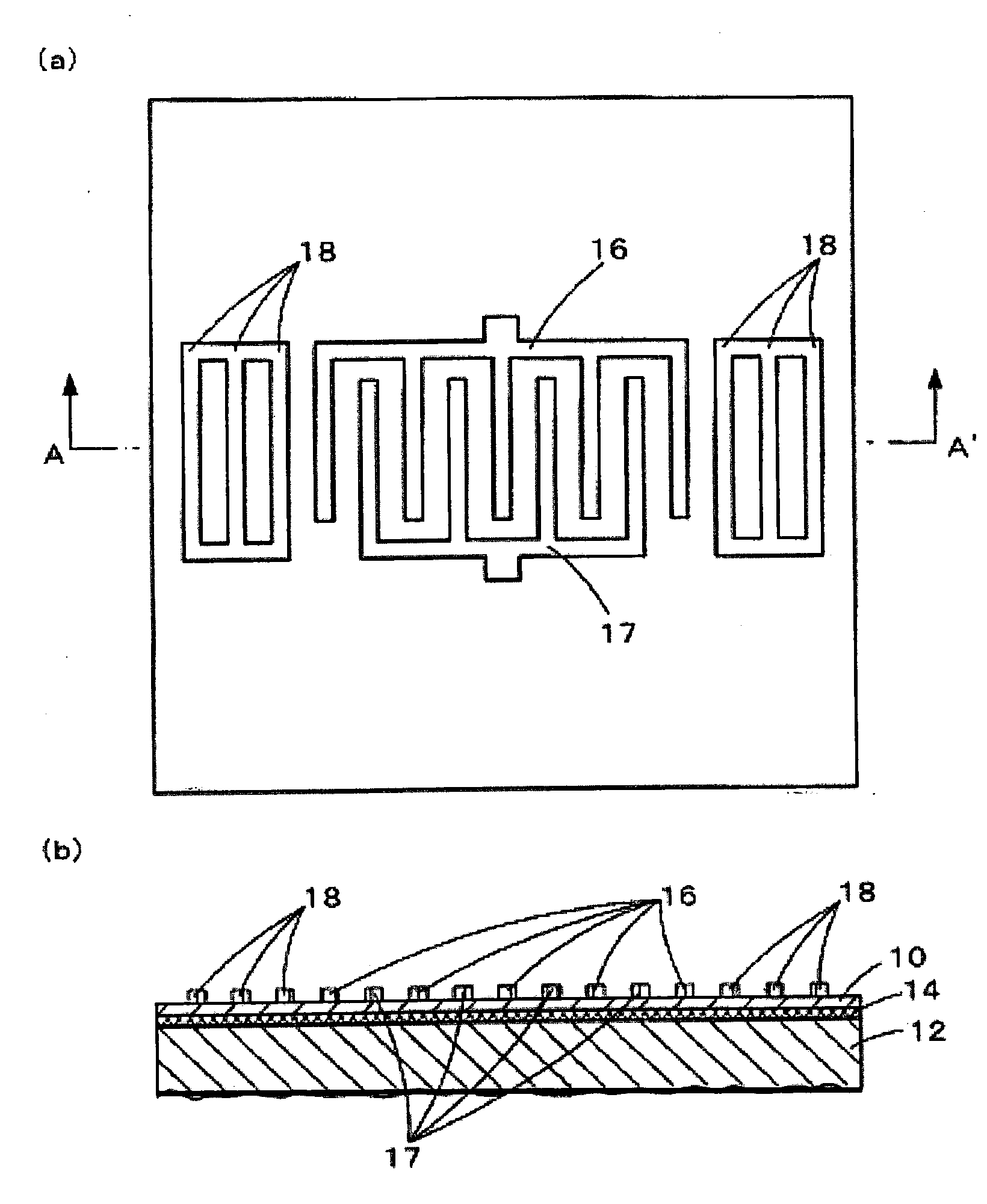
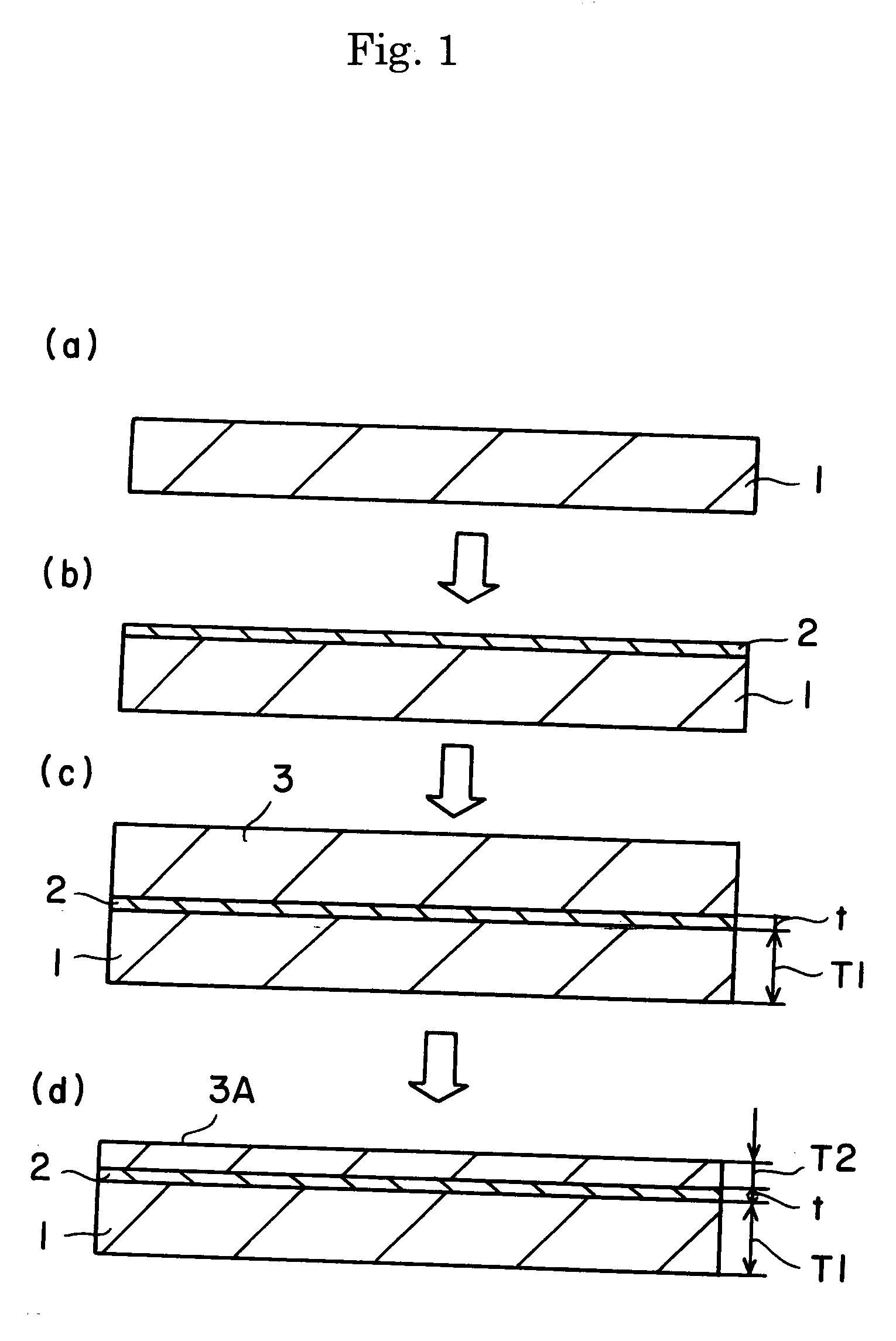
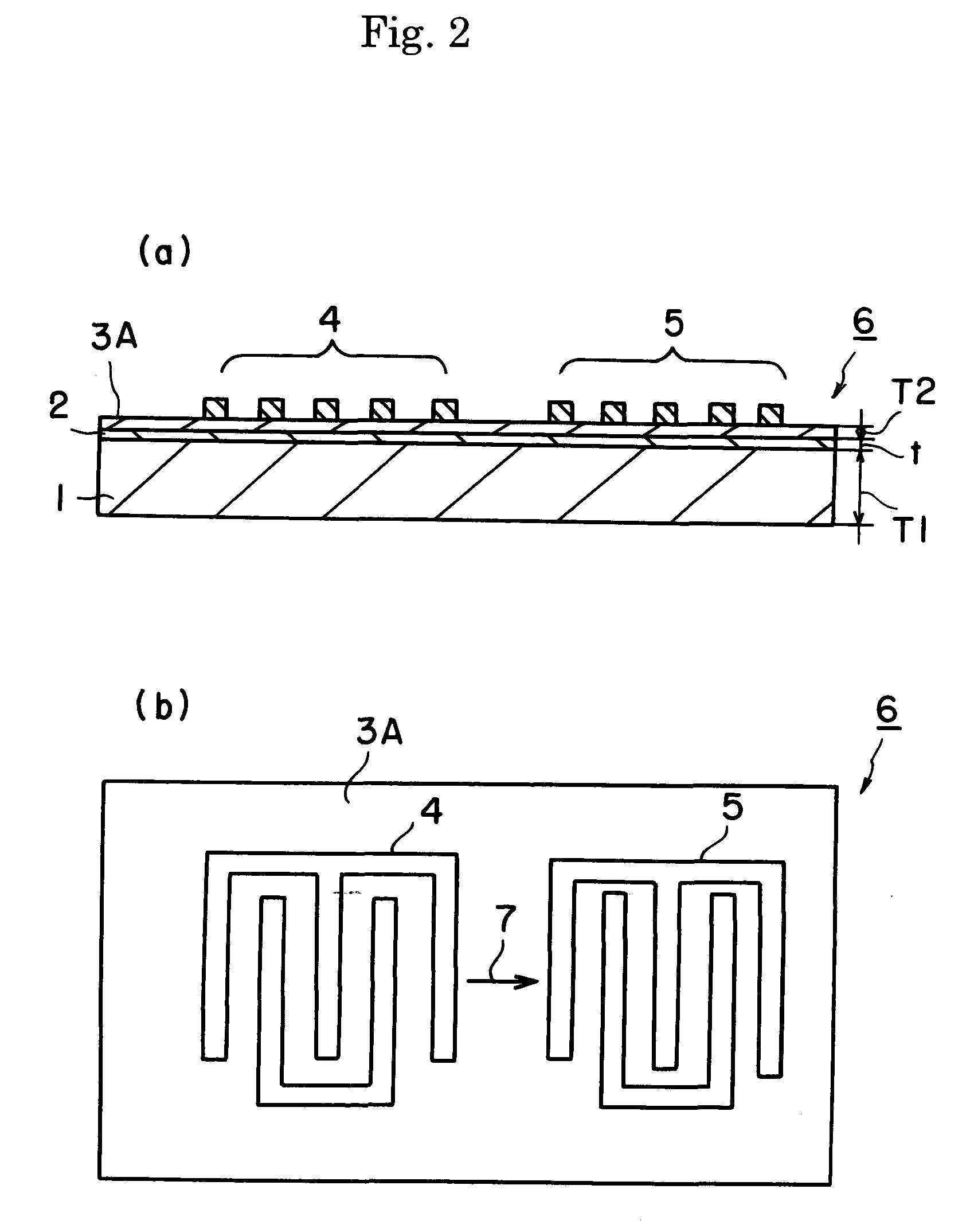
[0044]The surface acoustic wave device 6 of FIG. 2 was made using the manufacturing method shown in FIG. 1.

[0045]It should be noted that, as the substrate 3 was used a 36° Y-cut, X-propagation lithium tantalate substrate which had been cut out at an angle determined so as to form the rotated Y-cut plate and in which the direction of SAW propagation was set at the direction of the X-axis. The linear expansion coefficient in the SAW propagation direction X was 16 ppm / ° C. As the supporting substrate 1, a single crystal silicon substrate was used. The linear expansion coefficient in the SAW propagation direction X of the supporting substrate 1 was 3 ppm / ° C. The supporting substrate 1 was formed with a thickness T1 of 350 μm, the piezoelectric single crystal substrate 3 was formed with a thickness of 350 μm, and both the substrates were bonded together with the organic (acrylic) adhesive at 180° C. Then, the thickness of the piezoelectric single crystal substrate 3 was reduced to 30 μm...

example 2

[0048]Next, the surface acoustic wave device of FIG. 3 was made according to the same procedure as the Example 1. The thus obtained device was subjected to the same experiment as the Example 1 to prove that the temperature coefficient of frequency is considerably and critically improved by setting the thickness of the organic adhesive layer to 0.1 to 1.0 μm.


PUM


Abstract

A surface acoustic wave device has a supporting substrates, a propagation substrate 3A made of a piezoelectric single crystal, an organic adhesive layer 2 having a thickness of 0.1 to 1.0 μm and bonding the supporting substrate 1 and the propagation substrate 3A, and a surface acoustic wave filter or resonator provided on the propagation substrate. The temperature coefficient of frequency of the surface acoustic wave device can be thereby reduced.

Description

[0001]This application claims the benefit of Japanese Patent Application P2008-105407 filed on Apr. 15, 2008, the entirety of which is incorporated by reference.TECHNICAL FIELD[0002]The present invention relates to a surface acoustic wave device with superior temperature characteristics of frequency.BACKGROUND ARTS[0003]Surface acoustic wave (SAW) devices have been in extensive use as bandpass filters in communication equipments such as a cellular phone and the like. With the enhancement of the performance of cellular phone and the like, there is an increasing demand to enhance the performance of the filters using the surface acoustic wave devices.[0004]In the surface acoustic wave device, however, there is a problem of the passband shifts due to temperature changes. In particular, lithium niobate and lithium tantalate frequently used have high electromechanical coupling coefficients, and thus provide an advantage in achieving broad-band filtering characteristics. However, lithium n...

Claims


Application Information

Patent Timeline
Patent Type & Authority Applications(United States)
IPC IPC(8): H01L41/107H10N30/40
CPCH03H3/10H03H9/02834H03H9/02574
Inventor SUZUKI, KENJIYOSHINO, TAKASHI
Owner NGK INSULATORS LTD
Learn More