

Tunable Optical Array Device Comprising Liquid Cells
an array device and liquid cell technology, applied in the direction of liquid surface applicators, instruments, coatings, etc., can solve the problems of not being able to manufacture such large array devices, and not being able to meet the requirements of cost and precision. the effect of cos
- Summary
- Abstract
- Description
- Claims
- Application Information
AI Technical Summary
Benefits of technology
Problems solved by technology
Method used
Image

Examples
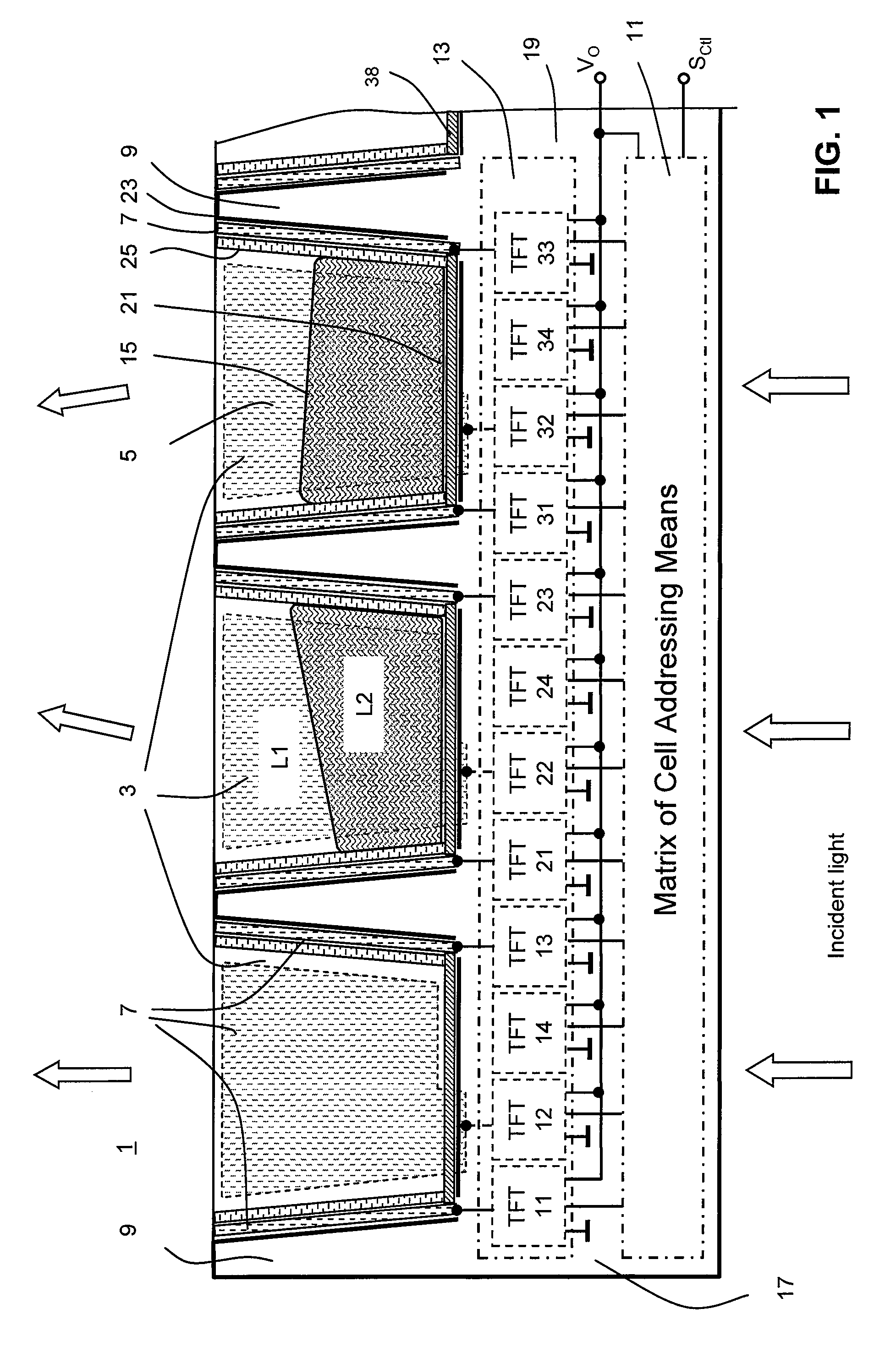
first embodiment
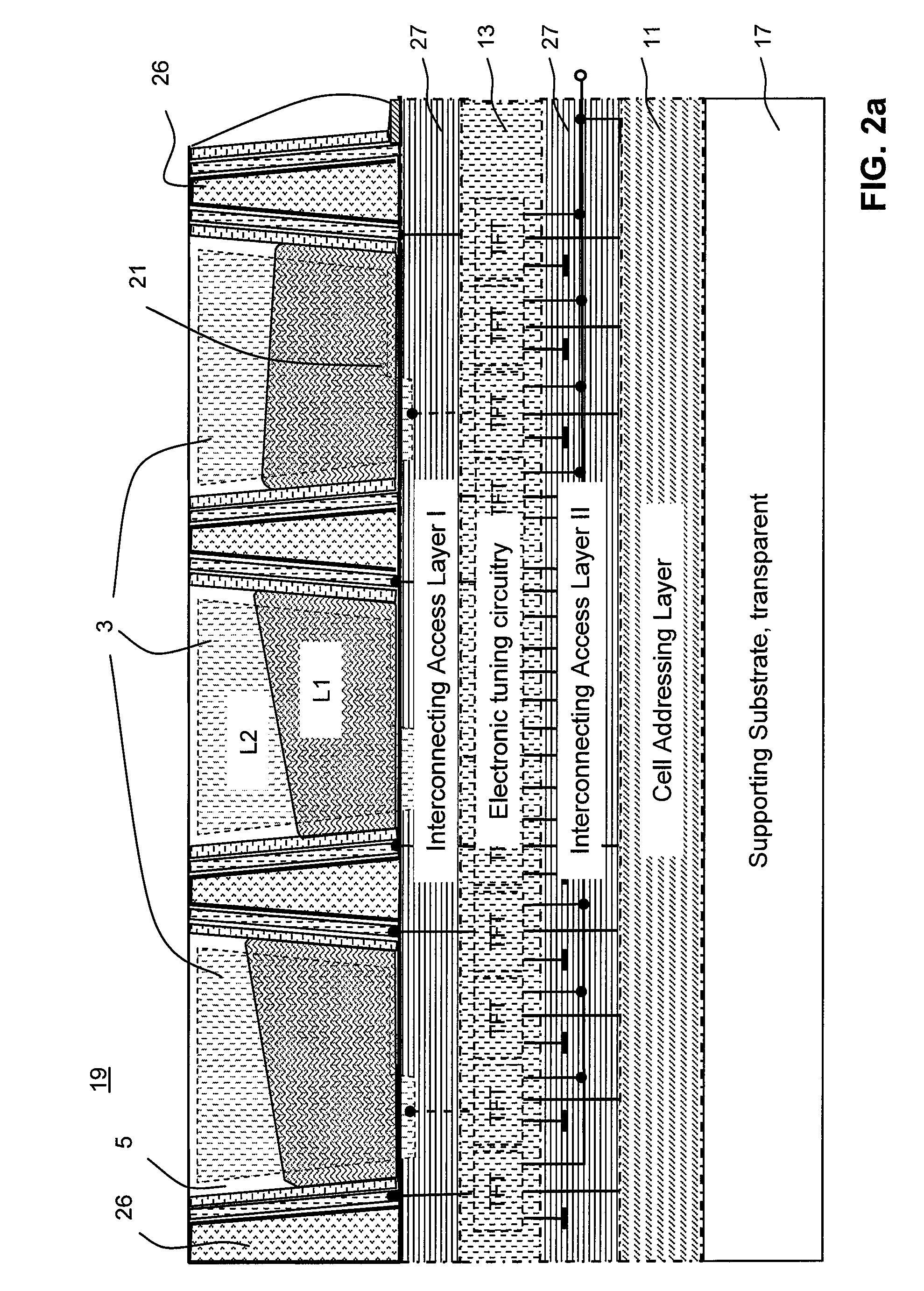
[0079]FIG. 2a, illustrates an extended embodiment of an optical array device according to the invention. The cell structure 3 is similar frustum shaped like the first embodiment; however a single compound unit 19 is formed by a multi layer structure comprising different substances.
[0080]The compound unit 19 comprises a cell layer 26 having a multitude of integrated cavities or penetrations forming the liquid cells 5 of the integrated cell structure 3. The cell layer 26 is manufactured by partially removing layer substance from the layer plate in a lift-up process according a lithographic pattern.
[0081]Additionally, on the supporting substrate 17 one or more additional layers are coated to provide specific substances like semiconductor substance, insulating substance, or conducting substance in order to manufacture the electronic tuning circuitry means 13, the cell addressing means 11 connected with the electronic tuning circuitry means 13, or interconnecting access means 27 for conn...
second embodiment
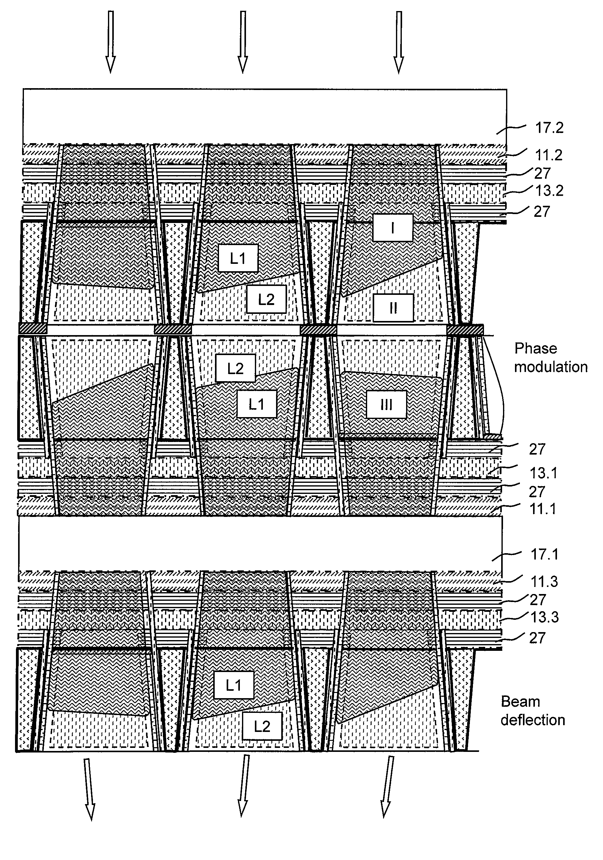
[0107]In a second embodiment the electronic tuning circuitry means drives the cell wall electrodes by different control voltages to move the interface area position to realize individually tunable phase modulator cells in a spatial light modulator. In other words the interface area position is altered such that the optical path length of the light passing through the liquid cell is altered.
[0108]FIG. 5 shows a further extended embodiment of an optical array device according to the invention comprising two supporting substrates 17.1 and 17.2, these have three cell structures. The upper two cell structures execute a first optical task. The lower cell structure executes a second optical task. The upper unit is designed similar to FIG. 4 to realize the function of a spatial light modulator modulating spatially the phase or optical pathlength in a wave field of coherent light. A second unit—shown in FIG. 5 on the bottom—is designed similar to FIG. 3. This unit moves or alters the propaga...
PUM
 Abstract
Description
Claims
Application Information