Beverage bottling or container filling plant having a beverage bottle or container labeling machine, and a beverage bottle or container labeling machine having a vacuum drum

a beverage bottling or container filling plant and beverage bottle or container technology, which is applied in the field of vacuum drums, can solve the problems of changing the cutting gap, affecting the operation of the vacuum drum, and not being able to substantially avoid the loss of friction, so as to achieve the effect of further enhancing the heat conductivity, cooling or chilling

Active Publication Date: 2009-10-22
KHS GMBH
View PDF7 Cites 3 Cited by
  • Summary
  • Abstract
  • Description
  • Claims
  • Application Information

AI Technical Summary

Benefits of technology

[0011]In accordance with the present application the distributor element, that does not rotate with the drum element, meaning that also the “first” sealing surface at this distributor element does not rotate with the drum element, is configured of a material which exhibits a substantially higher heat conductivity when compared to the material of the second sealing surface at the drum element that rotates. Thus, the distributor element of the rotary distributor and vacuum distributor that does not rotate with the drum element, operates as a heat sink, by means of which the frictional heat of the rotary distributor and vacuum distributor is removed. The material forming the second sealing surface at the drum element that rotates, furthermore, also serves as a heat barrier, so that alone by these measures a heating, at least an excessive heating, of the rotating drum element of the vacuum drum, which element is made otherwise from a metallic material, is substantially avoided, restricted, and / or minimized. The cooling, or chilling effect can be further enhanced by a suitable cooling, for example, by chilling ribs in the distributor element that does not rotate with the drum element of the rotary distributor, or vacuum distributor.

Problems solved by technology

However, this arrangement has the disadvantage that friction losses cannot substantially be avoided, restricted, and / or minimized and the resulting frictional heat flows directly into the drum element made of the metallic material, so that the drum element is heated during the operation to a considerable extent, while there does not arise, through the plastic, or synthetic material of the drum element of the rotary distributor, or vacuum distributor, that does not rotate with the drum element, an appreciable heat reduction, inasmuch as in comparison to the metallic material, the plastic, or synthetic material does not reduce the frictional heat, or in a very low amount.
The warming, or heating, or, possibly, overheating of the drum element leads to the fact that there arise operational changes, for example, changes of the diameter of this drum element which changes impair the operation of the vacuum drum.
In one possible embodiment, when the vacuum drum is configured to operate as a cutting drum of a cutting arrangement, the frictional heat that is introduced into the drum element leads to changes of the cutting gap which has negative consequences with respect to the quality of the cut and / or the processing speed.
Disadvantageously in such devices are the substantially constructive and apparatus-related expenditures and the high energy costs caused by the heating.

Method used


Image

  • Beverage bottling or container filling plant having a beverage bottle or container labeling machine, and a beverage bottle or container labeling machine having a vacuum drum
  • Beverage bottling or container filling plant having a beverage bottle or container labeling machine, and a beverage bottle or container labeling machine having a vacuum drum
  • Beverage bottling or container filling plant having a beverage bottle or container labeling machine, and a beverage bottle or container labeling machine having a vacuum drum

Examples


Embodiment Construction

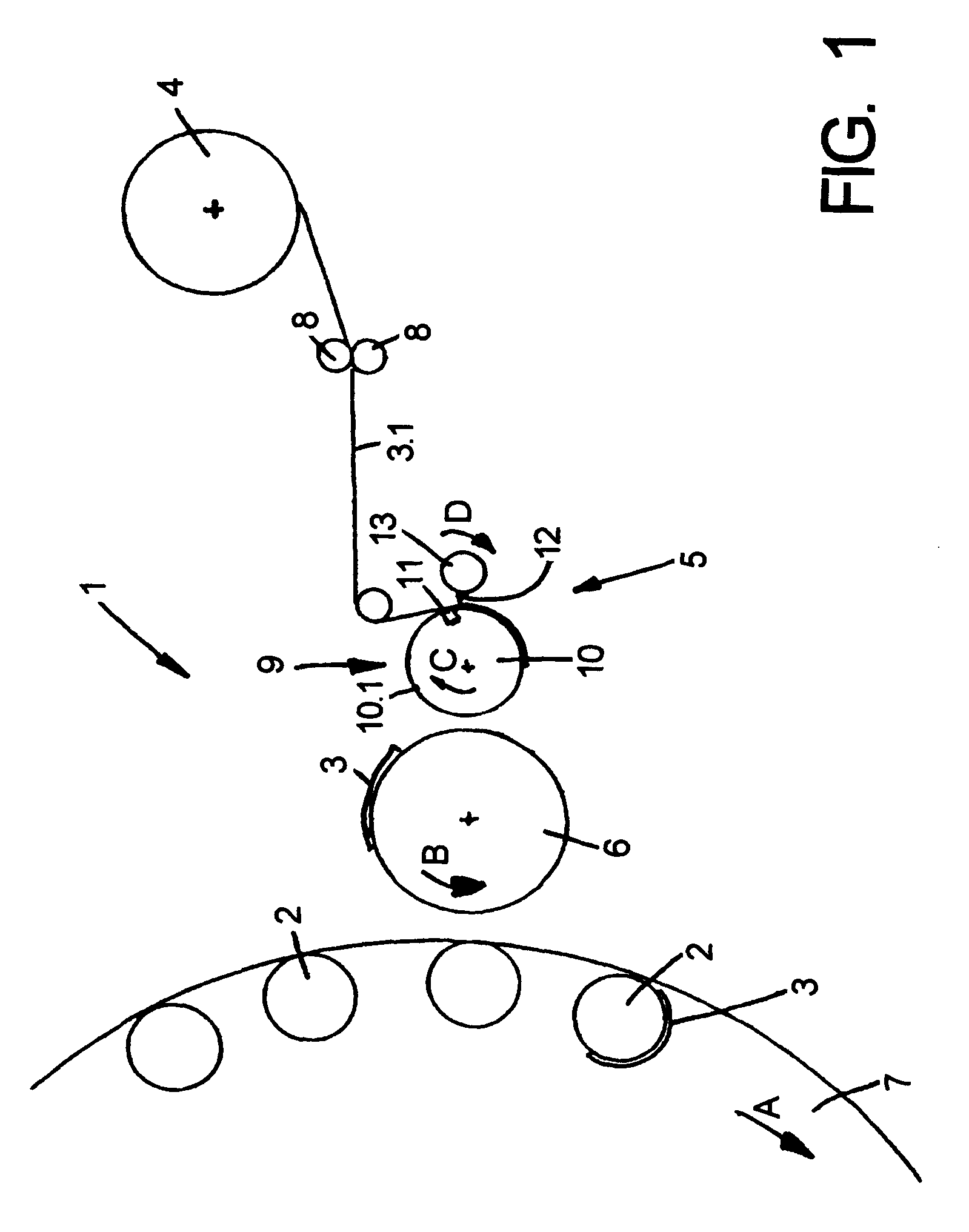
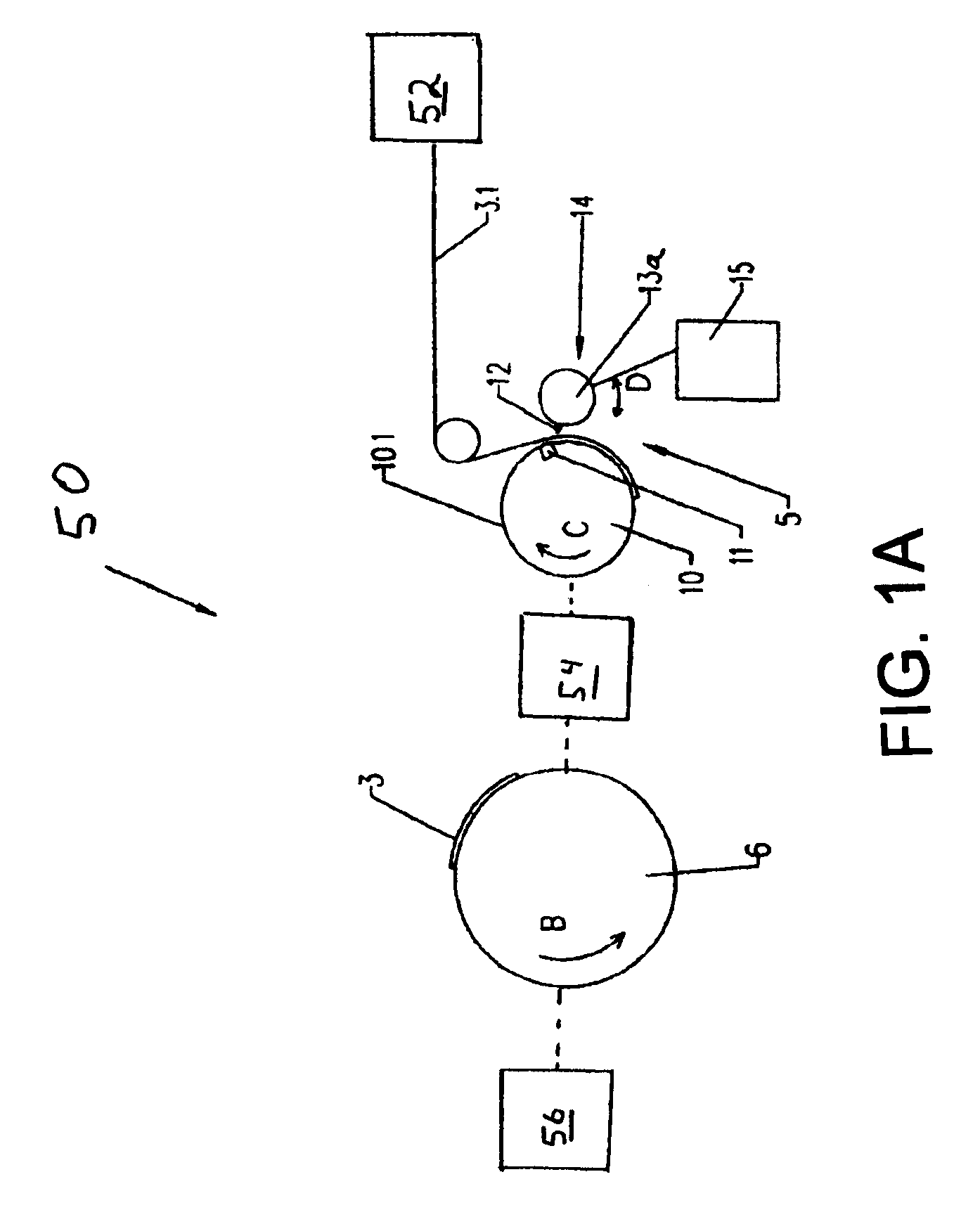
[0024]In the figures a labeling arrangement 1 is configured to operate with a labeling machine for labeling of bottles, or such like containers 2 with so-called Roll-Fed labels 3 which are drawn off from a stock roller 4 of an endless, tape-shaped label material 3.1; and the labels 3 are cut off in a cutting arrangement 5 of the labeling arrangement 1 with the respective length that is required and / or desired for a label 3, from the label material 3.1. The labels 3 established in this manner are passed, by means of a labeling drum and transfer drum 6, onto the containers 2 which are moving there along on a rotor 7 that is rotating about a vertical machine axis of the labeling machine in the labeling arrangement 1; and the labels 3 are secured to the containers 2. The rotation directions of the rotor 7 and of the transfer drum 6 are respectively indicated by the arrows A or B.

[0025]In other words, in one possible embodiment, FIG. 1 depicts a labeling arrangement 1. Labeling arrangeme...


PUM

PropertyMeasurementUnit
lengthaaaaaaaaaa
vacuumaaaaaaaaaa
rotationaaaaaaaaaa

Abstract

Beverage bottling or container filling plant having a beverage bottle or container labeling machine, and a beverage bottle or container labeling machine having a vacuum drum. The abstract of the disclosure is submitted herewith as required by 37 C.F.R. §1.72(b). As stated in 37 C.F.R. §1.72(b): A brief abstract of the technical disclosure in the specification must commence on a separate sheet, preferably following the claims, under the heading “Abstract of the Disclosure.” The purpose of the abstract is to enable the Patent and Trademark Office and the public generally to determine quickly from a cursory inspection the nature and gist of the technical disclosure. The abstract shall not be used for interpreting the scope of the claims. Therefore, any statements made relating to the abstract are not intended to limit the claims in any manner and should not be interpreted as limiting the claims in any manner.

Description

CONTINUING APPLICATION DATA[0001]This application is a Continuation-In-Part application of International Patent Application No. PCT / EP2007 / 009370, filed on Oct. 29, 2007, which claims priority from Federal Republic of Germany Patent Application No. 10 2006 051 989.5, filed on Oct. 31, 2006. International Patent Application No. PCT / EP2007 / 009370 was pending as of the filing date of this application. The United States was an elected state in International Patent Application No. PCT / EP2007 / 009370.BACKGROUND[0002]1. Technical Field[0003]The present application relates to a vacuum drum for the use in container treatment machines, in one possible embodiment labeling machines, with a drum element that is journaled for rotation in a carrier arrangement and that is configured to be powered for rotation about a drum axis. The vacuum drum also comprises at least one vacuum channel that is configured in the drum element and opens into a vacuum opening, as well as comprises a rotary distributor ...

Claims


Application Information

Patent Timeline
Patent Type & Authority Applications(United States)
IPC IPC(8): B65B3/00B65B43/42B65B61/00B65B7/28
CPCB65C2009/1842B65C9/1803
Inventor DECKERT, LUTZ
Owner KHS GMBH
Why Eureka
Try Eureka