Pure ar gas shielded welding mig flux-cored wire and mig arc welding method

a technology of fluxcored wire and purified ar, which is applied in the direction of welding/cutting media/materials, welding apparatus, manufacturing tools, etc., can solve the problems of deterioration of the property of pure ar-mig welding, inability to use pure argon gas arc welding methods, and inability to achieve mig fluxcored wire welding, etc., to achieve low cost and stable pure ar-mig welding, high static tensile strength, and fatigue strength

Inactive Publication Date: 2009-10-22
KOBE STEEL LTD
View PDF9 Cites 40 Cited by
  • Summary
  • Abstract
  • Description
  • Claims
  • Application Information

AI Technical Summary

Benefits of technology

[0039]According to the present invention, conventional welding devices such as a torch can be used without being modified, and the wire compositions and shielding gases can be appropriately combined. Thereby, while greenhouse effect gases do not have to be used, and expensive metal resources

Problems solved by technology

Unlike the case where a base metal is an aluminum alloy metal, it has been considered that an inert gas arc welding method using pure argon is substantially impossible with gas shielded arc welding of steel materials.
However, in the case where oxidizing gases, such as CO2 and O2, exist, iron is inevitably oxidized in a molten state, and the property thereof is deteriorated thereby.
More specifically, because oxidizing gases are used, expensive elements unnecessary for the joint performance are used.
Hence, compared with the MAG welding and MIG welding methods in which arc is generated from the wire itself, the TIG welding method poses a drawback in that the efficiency is very low.
However, in the case of the welding wire disclosed in Japanese Unexamined Patent Application Publication No. 2006-205204, the manufacture is difficult, also the composition contains large amounts of elements such as Ni and Cr, so that the wire is expensive, and the

Method used


Image

  • Pure ar gas shielded welding mig flux-cored wire and mig arc welding method
  • Pure ar gas shielded welding mig flux-cored wire and mig arc welding method
  • Pure ar gas shielded welding mig flux-cored wire and mig arc welding method

Examples


examples

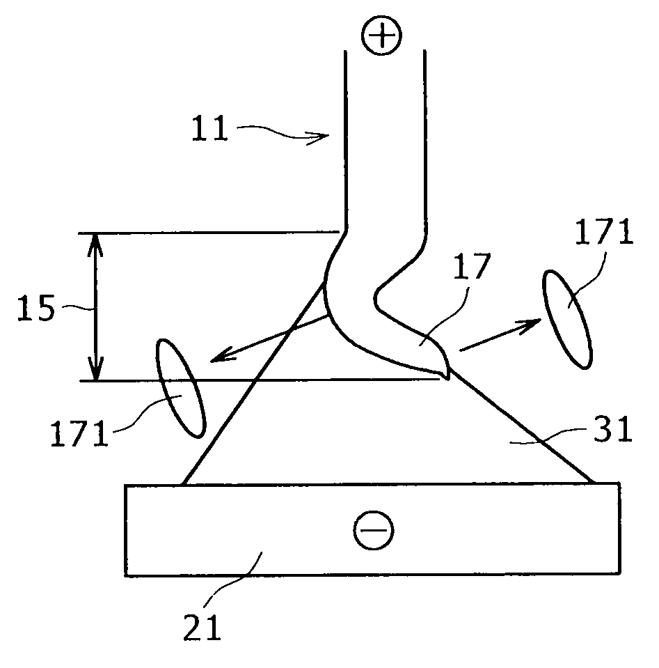
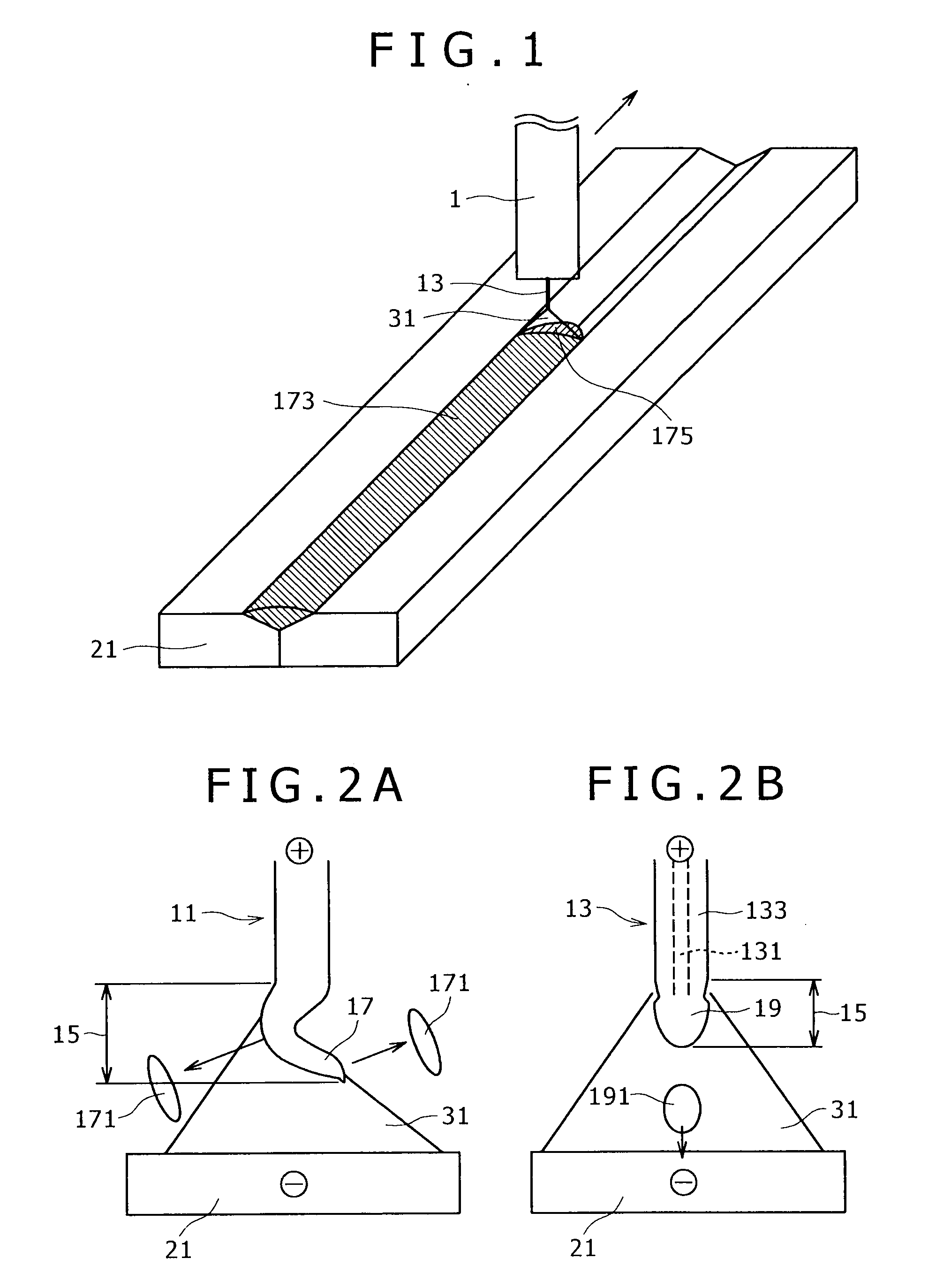
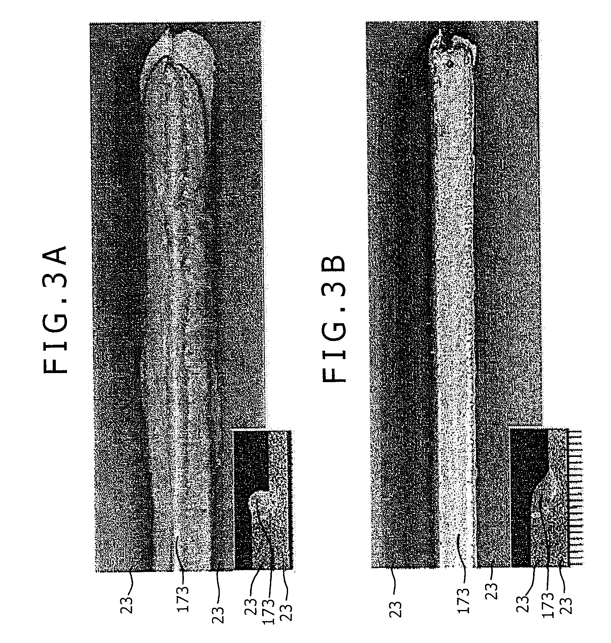
[0097]As Test 1, butt welding as shown in FIG. 1 was carried out using a SS400 steel sheet having a sheet thickness of 12 mm. Table 1 shows a composition of a flux-cored wire steel hoop used in the test. Using the steel sheet as an outer sheath, flux-cored wires having compositions shown in Tables 2-1, 2-2, 3-1, 3-2, 4-1 and 4-2 were manufactured. However, only Comparative Example Nos. 65 and 66 are solid wires 11. The respective elements are, basically, indicated as the positive addition elements, and “−” in the respective cell is indicated as a non-addition element. Further, the cells regarding P and S all indicate values as impurities, and the values shown therein are customary analysis values. The content of the respective element indicates the percentage on the basis of the total wire mass, but only the content of the respective item of iron powder indicates the percentage on the basis of total flux mass. Execution conditions applied to Test 1 were—shielding gas: JIS K 1105 Cla...


PUM

PropertyMeasurementUnit
Percent by massaaaaaaaaaa

Abstract

A pure Ar-MIG welding wire for welding steel according to the present invention is formed of a flux-cored wire. The flux-cored wire is formed in the manner that a formation formed by welding a carbon steel hoop into a pipe shape or a seamless pipe is used as an outer sheath, the outer sheath is filled with a flux, and a wire drawing process is performed. The flux accounts for 7 to 27 mass % of the total wire mass. The wire contains graphite in the amount of 0.16 to 2.00 mass % on the basis of the total wire mass and iron powder in the amount of 20 mass % on the basis of the total flux mass. According to the construction, neither expensive metal resource nor a greenhouse effect gas is used, slag and fume generation is inhibited, and a weld joint having a high static tensile strength and fatigue strength can be obtained.

Description

BACKGROUND OF THE INVENTION[0001]1. Field of the Invention[0002]The present invention relates to a pure Ar gas shielded welding MIG flux-cored wire and a MIG arc welding method. The wire is used to perform MIG arc welding of steel materials by use of pure Ar gas as shielding gas, and the method performs gas shielded arc welding while feeding the wire from a welding torch.[0003]2. Description of the Related Art[0004]Unlike the case where a base metal is an aluminum alloy metal, it has been considered that an inert gas arc welding method using pure argon is substantially impossible with gas shielded arc welding of steel materials. A reason is that in the case where the steel material is used as an electrode, electronic discharging requires an oxide having a low energy potential. With pure argon gas, an oxide is not formed either on a steel plate or wire end surface. Hence, generally, CO2 alone or a mixture of Ar and either CO2 or O2 is used as shielding gas. However, in the case where...

Claims


Application Information

Patent Timeline
IPC IPC(8): B23K9/09B23K35/22
CPCB23K9/173B23K35/0244B23K35/0266B23K35/383B23K35/362B23K35/368B23K35/3053
Inventor SUZUKI, REIICHIUMEHARA, YUNAKANO, TOSHIHIKO
Owner KOBE STEEL LTD
Why Eureka
Try Eureka