
Raman amplification in distributed optical fiber sensing systems

Inactive Publication Date: 2009-10-22
SCHLUMBERGER TECH CORP
View PDF2 Cites 38 Cited by
  • Summary
  • Abstract
  • Description
  • Claims
  • Application Information

AI Technical Summary

Benefits of technology

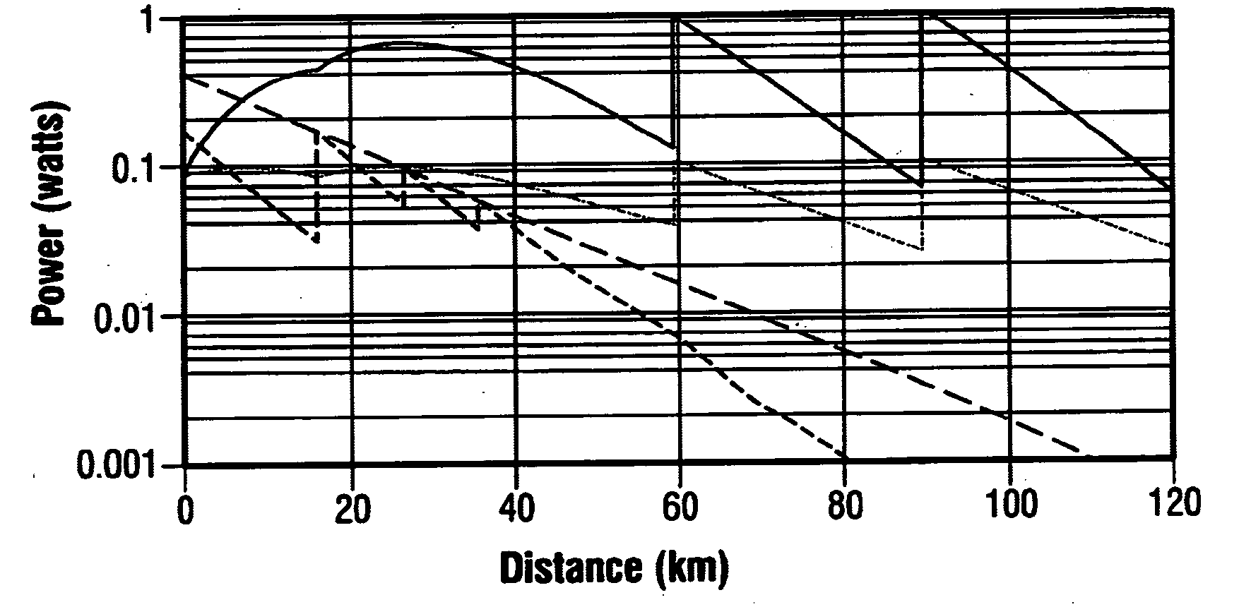
[0006]Accordingly, a first aspect of the present invention is directed to a method of providing Raman amplification in an optical fiber sensing system, comprising: generating a probe pulse of light at a probe wavelength; launching the probe pulse into a sensing optical fiber; generating pump light at a pump wavelength shorter than the probe wavelength; modulating the pump light to produce a time-varying intensity profile; launching the pump light into the sensing fiber such that the intensity of the launched pump light during launch of the probe pulse is different from the intensity at one or more other times; and propagating the pump light and the probe pulse along the sensing fiber to achieve Raman amplification of backscattered light produced by the probe pulse as it propagates.
[0007]Hence, the pump power is modulated such that the pump power travelling at about the same time as the probe pulse (allowing for chromatic dispersion effects, where different wavelengths have different propagation velocities in the fiber) is different from the pump power travelling in the fiber at other times, and in particular when the backscattered light is travelling back along the fiber. In this way, the Raman amplification experienced by the probe pulse and by the backscatter can be controlled separately, to optimise the performance of the system. The backscattered light can be amplified to give a bigger output signal from the fiber, thus improving the signal-to-noise ratio, while amplification experienced by the probe pulse (which gives a corresponding increase to the backscatter power so can be beneficial) can be limited to keep the probe pulse below the power threshold for nonlinear distortion effects.
[0008]In some embodiments, the intensity of the pump light during launch of the probe pulse is substantially zero so that the probe pulse experiences substantially no Raman amplification. This arrangement allows the maximum probe pulse power that tolerates nonlinear effects to be used at launch, so that high backscatter levels are received from the front part of the fiber, while backscatter produced at all points along the fiber is amplified as it propagates back along the fiber and meets the oncoming pump power.
[0009]Alternatively, the intensity of the pump light during launch of the probe pulse may be greater than zero, so that the probe pulse experiences some Raman amplification. While the initial probe pulse power should be reduced so that the Raman amplification does not push it above the nonlinear threshold, thus also reducing the initial backscatter power, the probe pulse power can be maintained at a higher level over a longer distance than with a zero pump power at probe launch. Backscatter levels are thus higher over more of the fiber, thereby extending the range of the system. Preferably, the intensity of the pump light during the launch of the probe pulse is sufficient to amplify the probe pulse to an intensity below a threshold above which the probe pulse would be distorted by nonlinear effects, so that the benefits of an extended range are not offset by a degradation in signal quality resulting from nonlinear distortion.
[0010]The method may further comprise introducing a time delay into forward propagating light in the sensing fiber at either the probe wavelength or the pump wavelength such that after the delay, the probe pulse overlaps a part of the intensity profile of the pump light having a greater intensity than the part overlapped by the probe pulse before the delay, and experiences Raman amplification. The time delay can be introduced at any location along the sensing fiber, so that the probe pulse can begin to experience Raman amplification at a selected point, such as that where the probe power has decayed sufficiently that nonlinear effects will not become a problem if the pulse is amplified. Thus, the time delay may be introduced such that the intensities of the probe pulse and of the pump light with which it overlaps after the delay are such that the probe pulse is amplified by the pump light to an intensity below a threshold above which the probe pulse would be distorted by nonlinear effects. The probe pulse can thereby be maintained near a maximum power level that avoids distortion over some considerable distance, particularly if several time delays are introduced so that the pump power available to amplify the probe pulse is repeatedly boosted. Also, in the case of a non-zero pump power at probe launch, the pump energy that has been depleted by conversion to the probe wavelength during Raman amplification can be replenished by the time shift, to maintain probe amplification.
[0011]The invention thus offers various improvements to Raman amplification of the various wavelengths propagating in a sensing fiber. By starting with high probe pulse power and a moderate (or zero) pump power at the launching end of the fiber, the near-end backscatter signals can be made strong due to a strong probe and yet amplification of the backscatter signals can still be maximised. Further along the fiber, the amplified backscatter signals are reduced because of the losses experienced by the probe and also a reduction of the Raman gain, since the pump is also attenuated by propagation losses. Introducing a relative delay between the modulated pump and the probe pulse allows the probe pulse to be switched from a low power to a high power region of the pump waveform, to increase Raman amplification. This also allows the depleted power that travels with the probe pulse to be replenished.

Problems solved by technology

Clearly, the gains could be balanced more effectively, but a fundamental problem with such a system is that the gain for the probe pulse cannot be adjusted independently of that for the backscatter.
In addition, the gain experienced by the probe pulse depletes the pump power locally, which means that the probe pulse is amplified when it is strongest, and then when its intensity has decayed there is no more pump power available to amplify it.
A drawback of this approach, however, is that the probe pulse is not amplified uniformly since one of its edges overlaps with the pump pulse before the remainder of the probe pulse and thus this edge receives all the amplification.
As a result, distortion of the probe pulse may result which in turn might cause non-linear effects, notably self-phase modulation.
In addition, this approach does not allow the returning backscattered light to be amplified at the same time, because the probe power is confined to the duration of the probe pulse.

Method used


Image

  • Raman amplification in distributed optical fiber sensing systems
  • Raman amplification in distributed optical fiber sensing systems
  • Raman amplification in distributed optical fiber sensing systems

Examples


Embodiment Construction

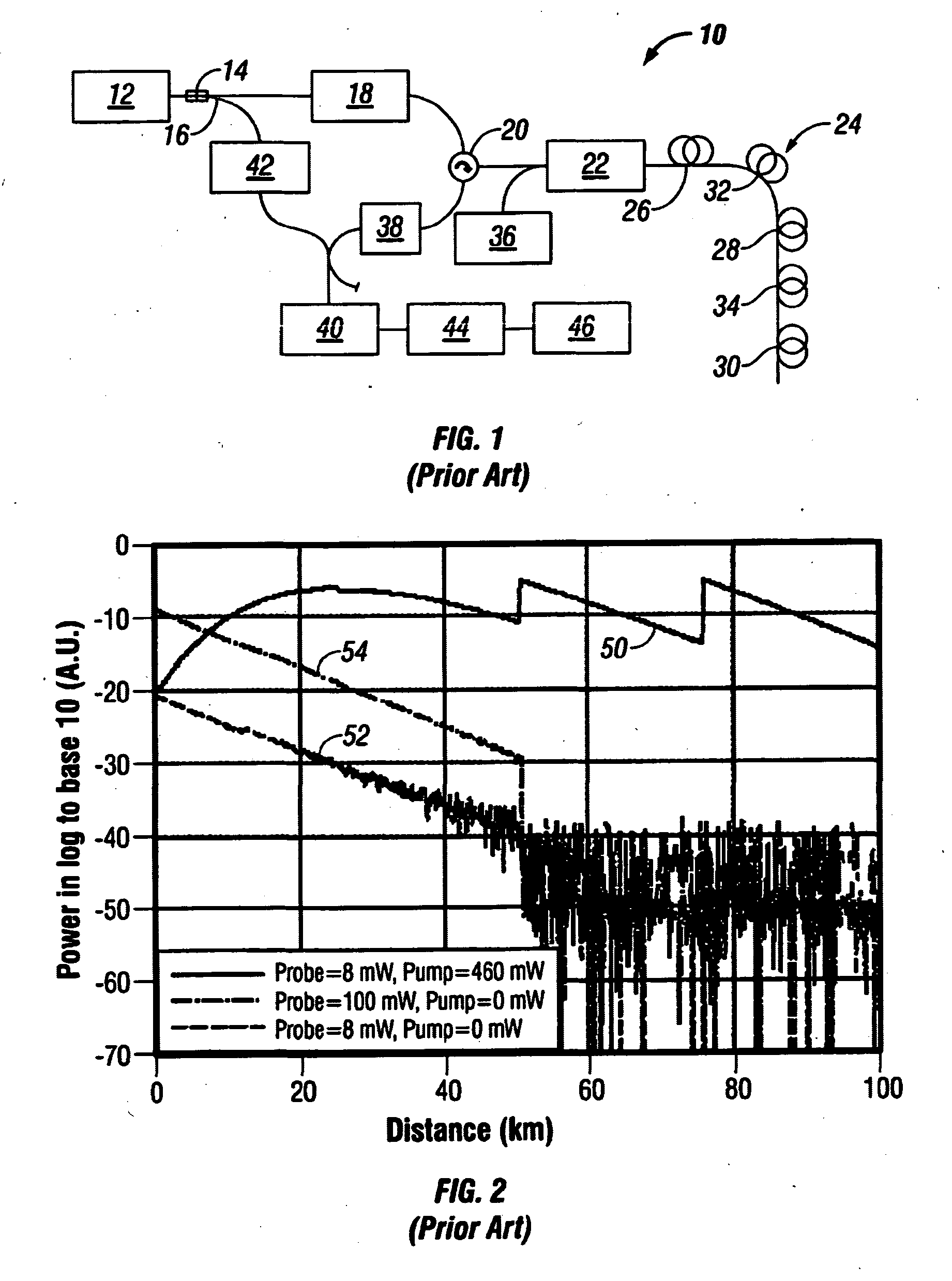
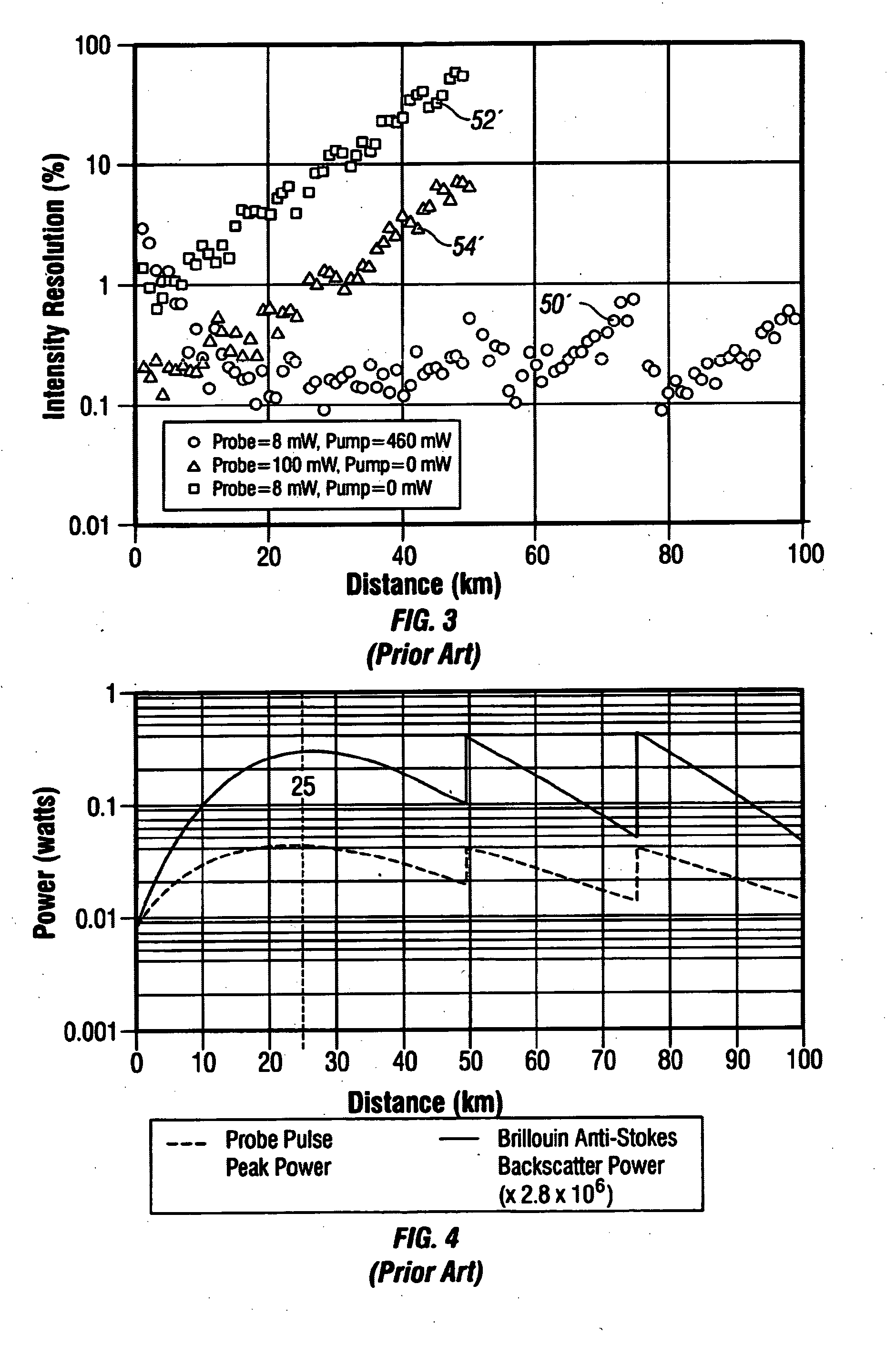
[0031]FIG. 1 shows a schematic diagram of a known optical time domain reflectometer system [1] intended to measure Brillouin backscattered light arising from the propagation along a deployed optical fiber of a probe pulse launched into the fiber. Similar systems can measure Raman backscattering (Stokes and anti-Stokes light) and / or direct backscatter at the wavelength of the probe pulse. The system 10 comprises an optical source 12, such as a continuous-wave narrowband laser operating at 1550 nm, the output of which is passed through an isolator 14 (optional) before being divided between two branches by a splitter 16. Light in a first branch enters a pulse amplifier module 18 which amplifies and modulates the light to produce probe pulses, which may have a duration of about 100 ns, for example. Each probe pulse leaves the pulse amplifier module 18 and enters a first port of an optical circulator 20, the second port of which launches the pulses (via a polarisation scrambler 22) into ...


PUM


Abstract

A method of providing Raman amplification in an optical fiber sensing system, comprises generating a probe pulse of light and launching the pulse into a sensing optical fiber, generating pump light at a shorter wavelength and modulating it to produce a time-varying intensity profile, and launching the pump light into the sensing fiber. such that the intensity of the launched pump light during launch of the probe pulse is different from the intensity at other times. Raman amplification of backscattered light produced by the probe pulse as it propagates along the fiber is achieved, as is amplification of the probe pulse if the pump power is non-zero during launch of the probe pulse.

Description

BACKGROUND OF THE INVENTION[0001]1. Field of the Invention[0002]The present invention relates to improvements in the use of Raman amplification in distributed optical fiber sensing systems, such as optical time domain resolution systems.[0003]2. Description of Related Art[0004]There is an interest in extending the range of distributed optical fiber sensors, in which backscattered light produced by a propagating probe pulse is collected to yield measurements of parameters associated with the fiber. Of particular interest are systems based on Brillouin and / or Rayleigh backscatter. A recent system [1] proposed a combination of distributed Raman amplification over the first 50 km of a sensing fiber and discrete erbium doped fiber amplifiers at 50 and 75 km, and was demonstrated to achieve 100 km range in the case of the determination of the Brillouin frequency shift with a resolution of well below 1 MHz (equivalent to better than 1 K resolution). To achieve this, continuous-wave pump po...

Claims


Application Information

Patent Timeline
IPC IPC(8): G02B6/00H01S3/30H04B10/291
CPCG01M11/319G01D5/353G01D5/35364G01N2021/638G01D5/35383H01S3/06754H01S3/094076H01S3/302H04B10/2916G01D5/35358G01N21/47
Inventor HARTOG, ARTHUR H.
Owner SCHLUMBERGER TECH CORP
Learn More