

Nano-crystalline, magnetic alloy, its production method, alloy ribbon and magnetic part
a technology of magnetic alloys and nano-crystalline materials, applied in the direction of magnetic materials, magnetic bodies, electrical equipment, etc., can solve the problems of large core loss, unsuitable high-power applications of ferrite, and difficult to produce inexpensive and high-magnetically-charged silicon steel plates, etc., to achieve low coercivity and core loss, high saturation magnetic flux density, and low cost
- Summary
- Abstract
- Description
- Claims
- Application Information
AI Technical Summary
Benefits of technology
Problems solved by technology
Method used
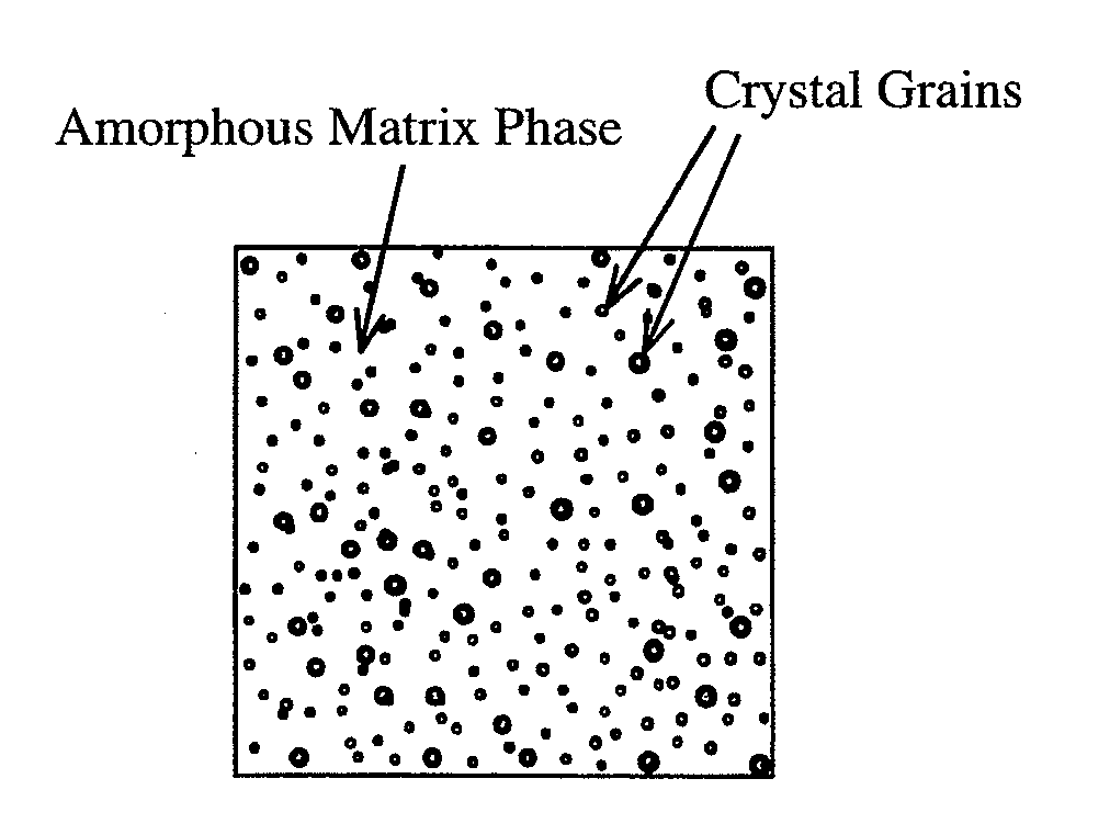
Image

Examples
example 1
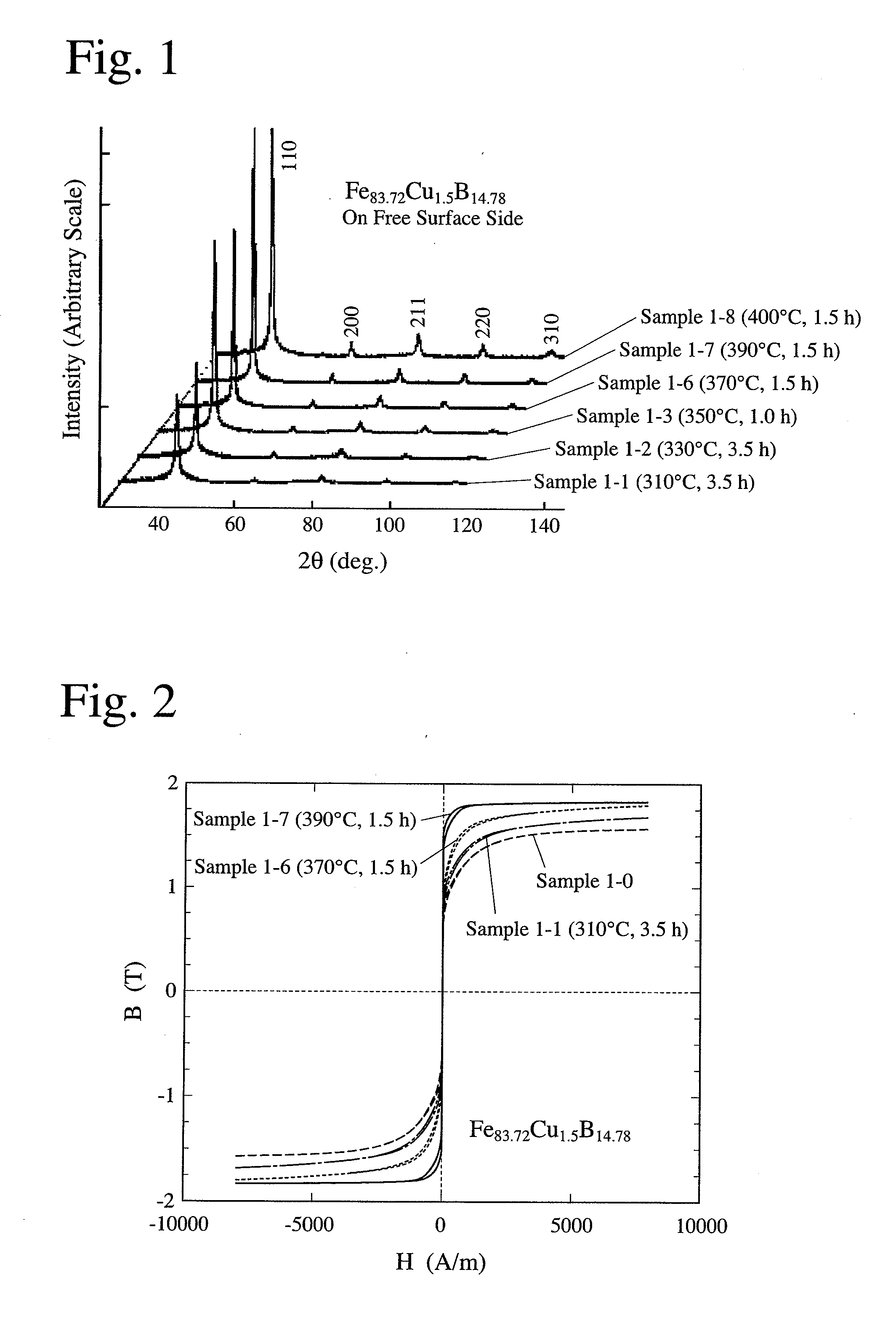
[0079]An alloy ribbon (Sample 1-0) of 5 mm in width and 18 μm in thickness obtained from an alloy melt having a composition represented by Fe83.72Cu1.5B14.78 (atomic %) by a single-roll quenching method was heat-treated at a temperature-elevating speed of 50° C. / minute under the conditions shown in Table 1, to produce magnetic alloys (Samples 1-1 to 1-8). Each Sample was measured with respect to X-ray diffraction, the volume fraction of crystal grains and magnetic properties. The measurement results of magnetic properties are shown in Table 1.
[0080](1) X-ray Diffraction Measurement
[0081]FIG. 1 shows the X-ray diffraction pattern of each sample. Although the diffraction of α-Fe was observed under any heat treatment conditions, it was confirmed from the half-width of a peak of a (310) plane obtained by the X-ray diffraction measurement that there was no lattice strain. The average crystal diameter was determined by the formula of Scherrer. There was a clear peak particularly when the ...
example 2
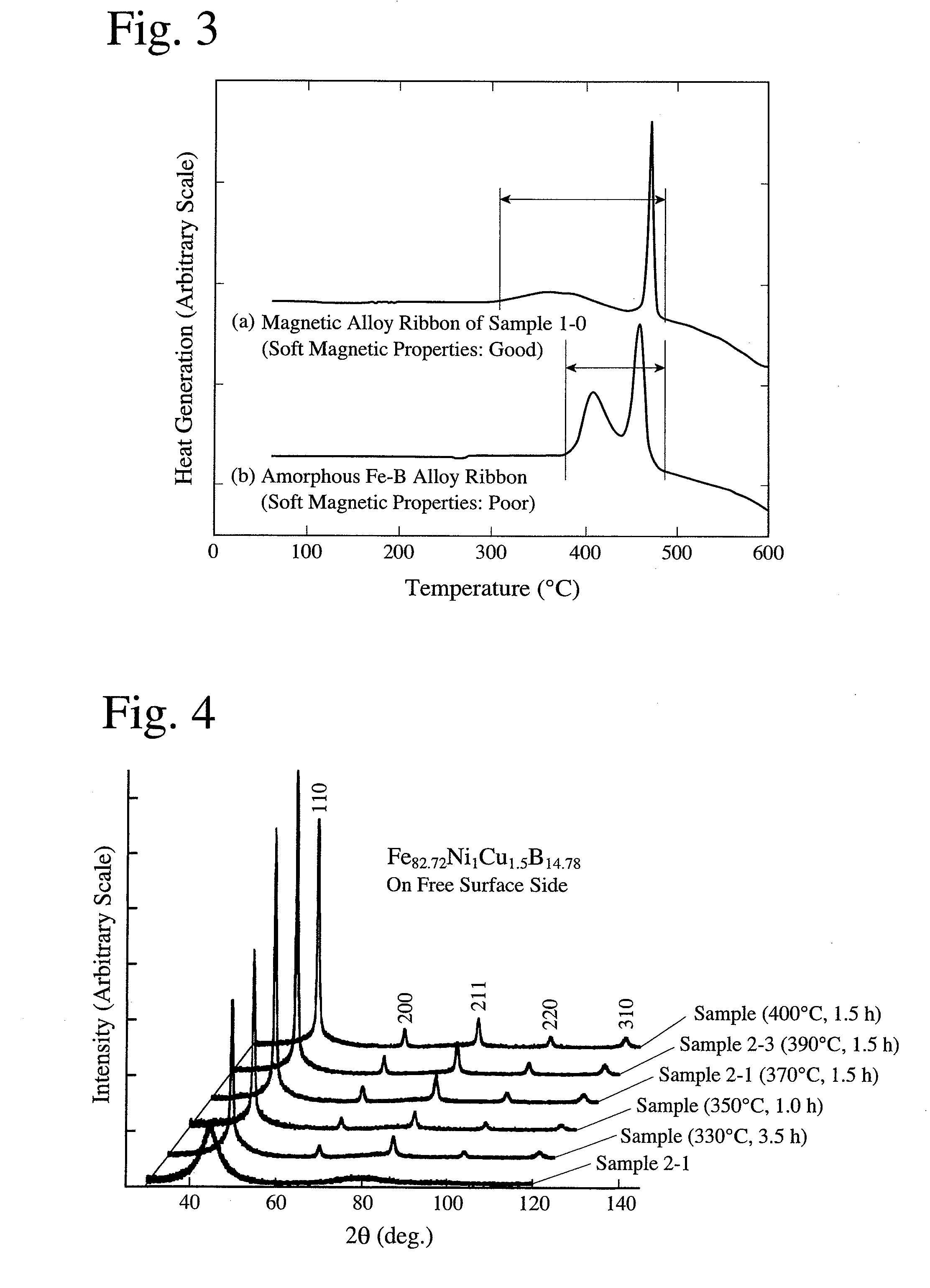
[0087]An alloy ribbon (Sample 2-0) of 5 mm in width and 18 μm in thickness obtained from an alloy melt having a composition represented by Fe82.72Ni1Cu1.5B14.78 (atomic %) by a single-roll quenching method was heat-treated at a temperature-elevating speed of 50° C. / minute under the conditions shown in Table 2, to produce magnetic alloys of Samples 2-1 to 2-4. Each sample was measured with respect to X-ray diffraction and magnetic properties. The measurement results of magnetic properties are shown in Table 2.
[0088]FIG. 4 shows the X-ray diffraction pattern of each sample. When the heat treatment temperature TA was low, there was a diffraction pattern in which a halo by the amorphous phase and peaks by crystal grains having a body-centered-cubic structure (bcc) were overlapping, but as the TA was elevated, the amorphous phase decreased, leaving the peaks of the crystal grains predominant. The average crystal diameter determined from the half-width of a peak of a (310) plane (=about 1...
example 3
[0090]An alloy ribbon of 5 mm in width and 20 μm in thickness (Sample 3-0) obtained from an alloy melt having a composition represented by Fe83.5Cu1.25Si1B14.25 (atomic %) by a single-roll quenching method in the atmosphere was heat-treated at a temperature-elevating speed of 50° C. / minute under the conditions shown in Table 3, to produce the magnetic alloys of Samples 3-1 and 3-2. Similarly, the magnetic alloy of Sample 3-4 was produced from an alloy ribbon (Sample 3-3) having a composition represented by Fe83.5Cu1.25B15.25, and the magnetic alloy of Sample 3-6 was produced from an alloy ribbon (Sample 3-5) having a composition represented by Fe83.25Cu1.5Si1B14.25. Each sample was measured with respect to X-ray diffraction, the volume fraction of crystal grains and magnetic properties. The measurement results of magnetic properties are shown in Table 3.
[0091]FIG. 6 shows the B-H curves of Samples 3-1 and 3-2. B8000, which increased as the heat treatment temperature TA was elevated,...
PUM
| Property | Measurement | Unit |
|---|---|---|
| Fraction | aaaaa | aaaaa |
| Diameter | aaaaa | aaaaa |
| Magnetic field | aaaaa | aaaaa |
Abstract
Description
Claims
Application Information