Eureka AIR delivers breakthrough ideas for toughest innovation challenges, trusted by R&D personnel around the world.

Varnish compositions for electrical insulation and method of using the same

a technology of varnish composition and electrical insulation, which is applied in the direction of liquid surface applicators, coatings, special surfaces, etc., can solve the problems of varnish chipping or cracking, significant thermal degradation, and more frequent maintenance intervals than desired

Active Publication Date: 2009-10-29
SHPP GLOBAL TECH BV
View PDF14 Cites 4 Cited by
  • Summary
  • Abstract
  • Description
  • Claims
  • Application Information

AI Technical Summary

Problems solved by technology

These varnish systems, however, have a glass transition temperature (Tg) significantly below 80° C. Thus, their performance at motor operating temperatures, usually about 160° C., can result in significant thermal degradation after extended operating times. In addition, such varnishes tend to chip or crack, particularly when subjected to vibrations accompanying locomotive operation.
Such UPR varnishes also have a high moisture absorption rate and their ester bonds are hydrolysable, which may result in more frequent maintenance intervals than desired.

Method used


Image

  • Varnish compositions for electrical insulation and method of using the same
  • Varnish compositions for electrical insulation and method of using the same
  • Varnish compositions for electrical insulation and method of using the same

Examples


example 1

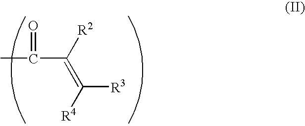
[0071]This is a theoretical example. The method described in U.S. Pat. No. 6,897,282 is used to make a methacrylate capped PPE compound illustrated in Formula II having an intrinsic viscosity of 0.06 dl / g. The PPE along with a dimethacrylate crosslinking agent and compatibilizing agent is then added to vinyl toluene in the amount of 40 percent by weight of the composition, along with 60 weight percent UPR to form a varnish composition. The crosslinking agent is SR348 (an ethoxylated bisphenol A dimethacrylate commercially available from Sartomer of Exton, Pa.), added in a weight ratio of 6:4:1 of PPE-plus-UPR / vinyl toluene / SR348. The compatibilizing agent is NANOSTRENGTH A250 SMB block copolymer consisting of a polystyrene-block-poly(1,4-butadiene)-block-poly(methyl methacrylate), added in a weight ratio of 6:4:2 of PPE-plus-UPR / vinyl toluene / compatibilizing agent. Then, 2% by weight of 2,5-bis-(t-butyl peroxy)-2,5-dimethyl-3-hexane (commercially available as TRIGONOX 101 from Akzo ...

example 2

[0072]A series of formulations A through F in Table 1 were prepared by blending methacrylate functional PPE (IV 0.09, available from SABIC Innovative Plastics, Inc., Selkirk, N.Y.), vinyl toluene (VT), a catalyzed unsaturated polyester solution in vinyl toluene (Von Roll 707C® available from Von Roll, Inc., Schenectady, N.Y.), and dicumyl peroxide (DCP) cure catalyst. Portions of these formulations were then degassed and cured at 160° C. for 2 hours followed by 180° C. for 1 hour. The remaining portions of formulations B, C, D, and E were found to phase separate on standing at room temperature.

TABLE 1ComponentFormulation(wt. %)ABCDEFPolyester10070.5866.6633.3425.0PPE11.7816.6733.3437.550.0Vinyl17.6416.6733.3337.550.0TolueneDCP0.440.501.001.131.50

[0073]Dynamic mechanical testing (DMA) according to ASTM D7028-07 was done on samples with the following dimensions: 2.5″×0.5″×0.125″ (6.4 cm×1.3 cm×0.32 cm). The Tg from this analysis is listed below. Thermal gravimetric analysis was also c...


PUM

PropertyMeasurementUnit
Temperatureaaaaaaaaaa
Timeaaaaaaaaaa

Abstract

A varnish composition for producing an electrically insulative thermoset coating is disclosed. The varnish composition includes a functionalized poly(phenylene ether) having at least one aliphatic unsaturated group and exhibiting an intrinsic viscosity in the range of about 0.06 to about 0.25 deciliter per gram, measured in chloroform at 25° C. The varnish composition further includes an unsaturated polyester resin or vinyl ester resin, a reactive liquid monomer, and a compatibilizing agent. When cured, the polymers and reactive liquid monomer form an electrically insulative thermoset.

Description

FIELD OF THE INVENTION[0001]The present invention is directed to varnish compositions for insulating electrical machinery and more particularly to poly(phenylene ether)-containing polymeric blends.BACKGROUND OF THE INVENTION[0002]Although the stator windings of electrical inductive devices, such as motors, are wound with magnet wire having enamel or other insulative coating thereon, it is often desirable to further coat the windings and seal them from the environment. When the motor is used in environments where the stator windings are exposed to moisture or abrasive materials, such as sand and dirt, it is often desirable to further protect the stator windings from the environment by means of an additional coating. For example, protection of the stator windings is desirable in blower motors utilized in the cooling systems for locomotive traction motors. Protection is also desirable in open motors utilized in driving pumps in oil field applications, which are exposed directly to blow...

Claims


Application Information

Patent Timeline
IPC IPC(8): B05D5/12C08L71/12C08L53/00
CPCC08G65/485C08L67/00C08L71/126C08L2666/18
Inventor O'BRIEN, MICHAEL J.IRWIN, PATRICIA CHAPMANLU, QIWEI
Owner SHPP GLOBAL TECH BV
Why Eureka
Eureka Blog
Learn More