Drive shaft assembly for a downhole motor

a technology of drive shaft and downhole motor, which is applied in the field of universal joints, can solve the problems of shortening affecting the service life of the universal joint, and unable to meet the requirements of torque transfer,

Active Publication Date: 2009-11-05
DRECO ENERGY SERVICES ULC
View PDF25 Cites 48 Cited by
  • Summary
  • Abstract
  • Description
  • Claims
  • Application Information

AI Technical Summary

Benefits of technology

[0036]In general terms, the apparatus of present invention is a drive shaft assembly, particularly but not exclusively suitable for incorporation into a downhole motor, incorporating a drive shaft formed with convexly spherical bearing surfaces on each end, plus end housings having concavely spherical bearing surfaces for receiving the spherical bearing surfaces of the drive shaft in slidable mating engagement, thereby facilitating omni-directional articulation between the drive shaft and the end housings while transferring axial thrust loads between the drive shaft and end housings across the spherical bearing interfaces at each end of the assembly. A pair of drive keys are swivellably mounted, in diametric opposition, to each end of the drive shaft, with the swivel axes of each pair of drive keys passing through the geometric centerpoint of the corresponding convexly spherical bearing surface of the drive shaft. The drive keys transmit the loads to the housings through flat contact faces that bear against bearing surfaces in complementary drive key slots formed in the end housings. Full and constant torque-transferring contact is thus provided between the swivelling drive keys and the end housings irrespective of any angular offset between the drive shaft and the end housings.

Problems solved by technology

In addition to the resultant inefficiency of torque transfer, the lack of constant engaging contact between the drive balls and the housing increases shock loading on the assembly, inducing fatigue stresses lending to shorten the service life of the universal joint.
As in CA 2,023,042, however, the Teale U-joint it has the drawback that only two torque-transmitting balls will be fully effective for torque transfer at any given time whenever the axes of the connecting shafts are not coincident.
The prior art universal joints fail to address several significant problems, the first of which is non-uniform and inefficient torque transfer in U-joints using circularly-arrayed torque-transfer elements such as the torque-transfer balls in CA 2,032,042 and U.S. Pat. No. 5,704,838, as discussed above.
However, all of the prior art U-joints, including the U-joint of CA 1,290,952, are limited in their torque-transfer capacity by both the available shear strength of their torque-transfer elements (e.g., drive balls or drive keys) and the effective contact area available for transferring torque-induced forces between the torque transfer elements and their corresponding resistive elements (e.g., pockets or slots in drive shafts or end housings).
Such torque-transfer limitations severely restrict the suitability and serviceability of known U-joints for use with higher-power PD motors that are now available in the market.
A further problem arises with known U-joints of the type that uses a spherical thrust bearing centrally disposed between the drive shaft and the end housing, as in CA 1,290,952, CA 2,032,042, CA 2,541,339, and U.S. Pat. No. 5,704,838.
Known U-joint designs cannot be readily adapted to withstand the higher thrust loads associated with newer high-power, high-torque PD power sections because the size of the spherical thrust bearing is constrained by the diameter of permissible drive shaft U-joints.

Method used


Image

  • Drive shaft assembly for a downhole motor
  • Drive shaft assembly for a downhole motor
  • Drive shaft assembly for a downhole motor

Examples


Embodiment Construction

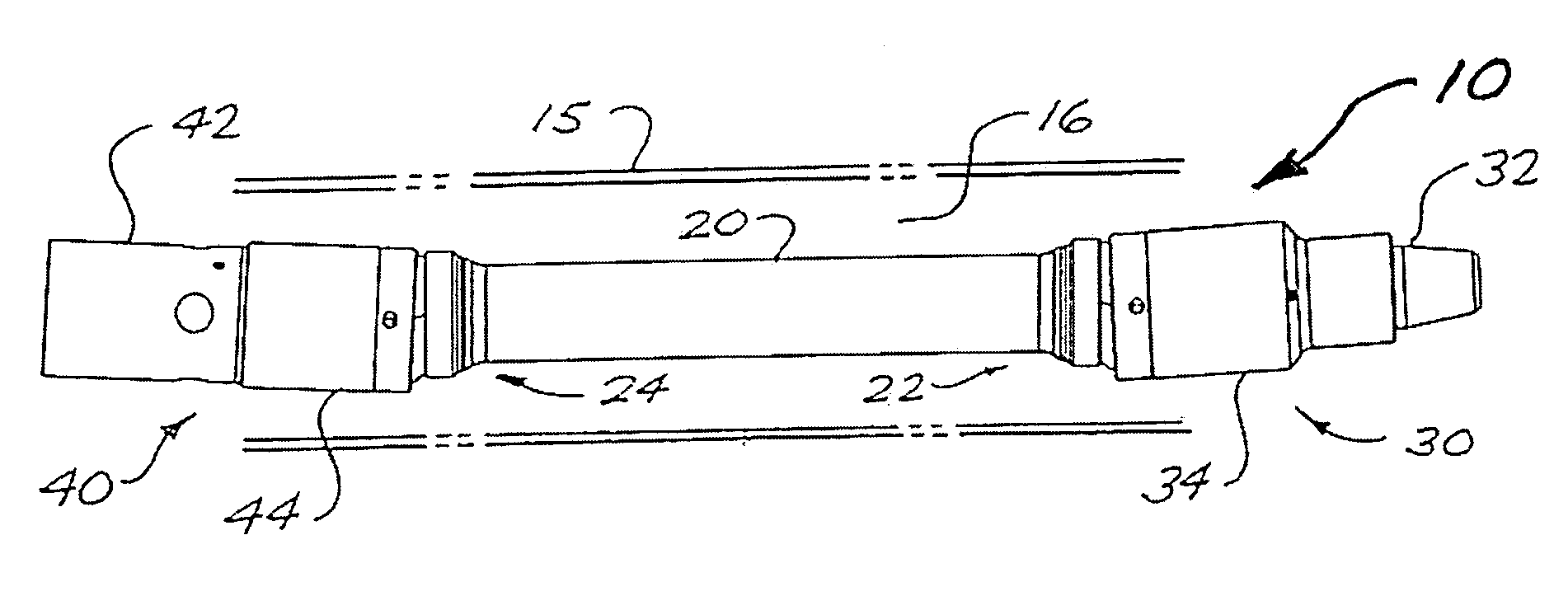
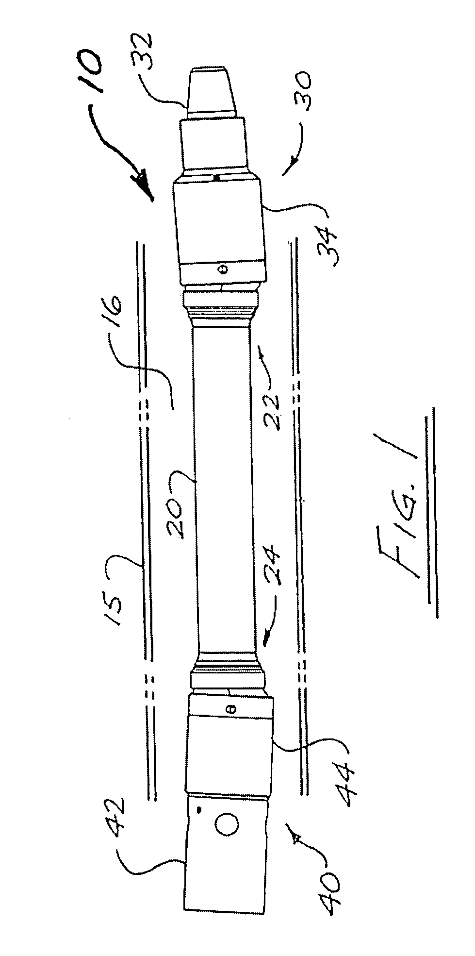
[0074]Referring to FIG. 1, a drive shaft assembly 10 in accordance with the present invention comprises a drive shaft 20 having an upper end 22 and a lower end 24, an upper end housing 30, and a lower end housing 40. When assembled within a downhole motor, drive shaft assembly 10 will be enclosed within a tubular drive shaft housing conceptually indicated by broken lines 15 in FIG. 1, thereby forming an annular space 16 between drive shaft housing 15 and drive shaft assembly 10.

[0075]Upper end housing 30 has a connector section 32, adapted for connection to the output shaft (not shown) of the power section of a downhole motor, and a coaxially contiguous socket section 34, adapted to receive upper end 22 of drive shaft 20 and to accommodate omni-directional rotation of drive shaft 20 therein, while transferring rotational torque and axial thrust loads from the output shaft to drive shaft 20. Lower end housing 40 has a connector section 42, adapted for connection to the mandrel of the...


PUM

PropertyMeasurementUnit
torqueaaaaaaaaaa
radiusaaaaaaaaaa
lengthaaaaaaaaaa

Abstract

A drive shaft assembly for a downhole motor includes a drive shaft formed with convexly spherical bearing surfaces on each end, and end housings with concavely spherical bearing surfaces for mating contact with the spherical bearing surfaces of the drive shaft, thereby facilitating omni-directional articulation between the drive shaft and the end housings while transferring axial thrust loads between the drive shaft and end housings across the interface of the mating spherical bearing surfaces. Torque is transferred between the drive shaft and end housings through two or alternatively four swivelling drive keys mounted to each end of the drive shaft and engageable with complementary drive key slots in the end housings. Full and constant torque-transferring contact is thus provided between the swivelling drive keys and the end housings irrespective of any angular offset between the drive shaft and the end housings, resulting from omni-directional articulation of the drive shaft relative to the end housing. The omni-directional center of rotation at each end of the drive shaft coincides with the geometric centerpoint of the corresponding convexly spherical bearing surface, which corresponds to the intersection of the drive shaft's rotational axis, the end housing's rotational axis, and the drive key swivel axis.

Description

CROSS-REFERENCE TO RELATED APPLICATIONS[0001]This application claims the benefit, pursuant to 35 U.S.C. 119(e), of U.S. Provisional Application No. 61 / 049,315, filed on Apr. 30, 2008, and said provisional application is incorporated herein by reference in its entirety.FIELD OF THE INVENTION[0002]The present invention relates in general to universal joints for transmitting torque between rotating shafts having intersecting but non-coincident rotational axes. More particularly, the invention relates to universal joints for drive shafts associated with downhole motors used in the oil and gas industry for drilling boreholes, especially in applications requiring transfer of large torque and axial thrust loads across the joint.BACKGROUND OF THE INVENTION[0003]In drilling a borehole (or wellbore) into the earth, such as for the recovery of hydrocarbons or minerals from a subsurface formation, it is conventional practice to connect a drill bit onto the lower end of an assembly of drill pipe...

Claims


Application Information

Patent Timeline
Patent Type & Authority Applications(United States)
IPC IPC(8): F16D3/72
CPCE21B4/02F16C3/02Y10T29/49826F16D3/20F16C11/0623F16D3/2052F16D3/2057
Inventor PRILL, JONATHAN RYANVOGHELL, MARK LOUIS PHILIP
Owner DRECO ENERGY SERVICES ULC
Why Eureka
Try Eureka