
Thermal isolation of electronic devices in submount used for leds lighting applications

a technology of leds and electronic devices, applied in semiconductor devices, semiconductor/solid-state device details, lighting and heating apparatus, etc., can solve the problems of increasing the difficulty of eliminating unwanted influence between these components, increasing the junction temperature, and increasing the difficulty of electronic devices to malfunction, etc., to achieve the effect of facilitating heat dissipation and low thermal conductivity of silicon oxid

Inactive Publication Date: 2009-11-12
NXP BV
View PDF51 Cites 17 Cited by
  • Summary
  • Abstract
  • Description
  • Claims
  • Application Information

AI Technical Summary

Benefits of technology

[0011]The above objects, are obtained according to a first aspect of the present invention by an electronic device comprising a substrate, heat emitting electronics and other electronics. The electronic device further comprising means for thermal insulation and means for heat dissipation. The heat emitting electronics and the other electronics are arranged on the substrate. The means for thermal insulation are arranged in the substrate to prevent heat dissipation from the heat emitting electronics along a first direction towards the other electronics, and the means for heat dissipation are arranged in the substrate to dissipate heat through the substrate along a second direction different than that of the first direction. Hence, it is accomplished a device in which thermal barriers and highly heat conductive paths in silicon submounts are arranged in order to dissipate heat and, as an advantage, to avoid excessive heating of electronic devices which are integrated in a submount.
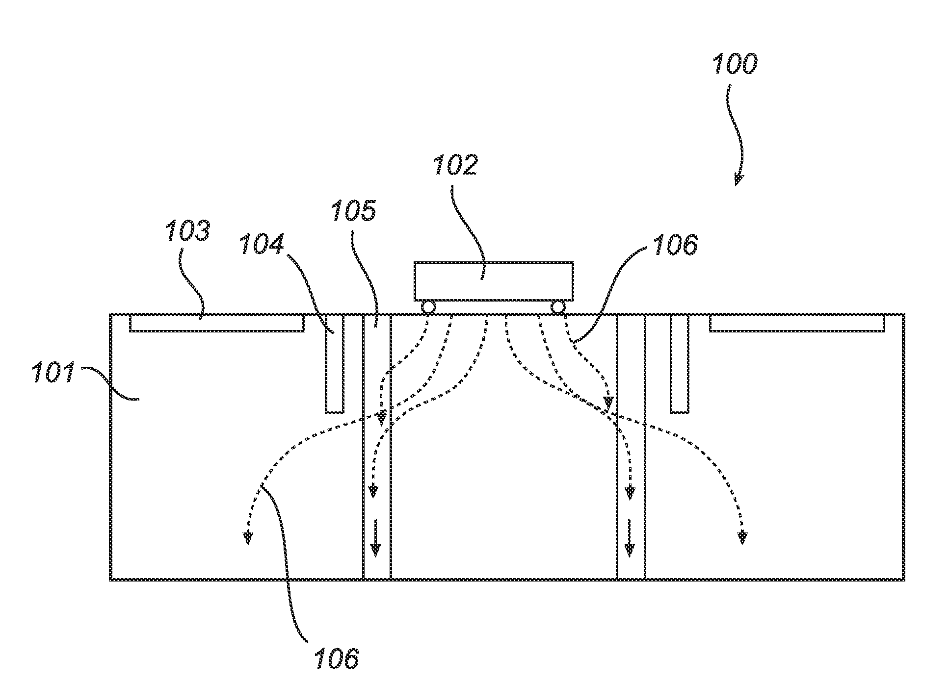
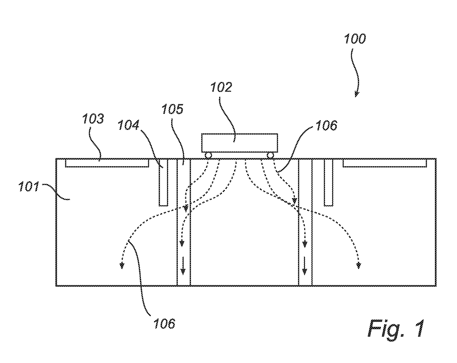
[0027]In other words, the invention according to one preferred embodiment is realized by a substrate comprising electronic devices which are isolated from heat generated by for instance a LED with a deep trench filled with silicon oxide. As the thermal conductivity of the silicon oxide is very low, it protects the components from the heat emitted by the LED. Substrate through vias filled with copper act as a heat pipe and facilitate the heat dissipation.

Problems solved by technology

Electronic devices comprise a growing number of electronic components, some of which generate large amount of excess heat and some of which are more sensitive to heat, causing the electronics to malfunction, sometimes temporary and sometimes permanently.
Consequently, it has become increasingly difficult to eliminate unwanted influence between these components, such as for instance due to heat emission.
As a consequence, this heat elevates the junction temperature of the LED and decrease the lifetime and the efficiency of it.
Furthermore, more and more frequently it occurs that the LED junction temperature is rising at levels higher than 150° C., sometimes even as high as 185° C. In this range of temperature, the functionality of the electronic devices is strongly affected and impact the good light control of a Multi-chip module.

Method used


Image

  • Thermal isolation of electronic devices in submount used for leds lighting applications
  • Thermal isolation of electronic devices in submount used for leds lighting applications
  • Thermal isolation of electronic devices in submount used for leds lighting applications

Examples


Embodiment Construction

[0059]FIG. 1 shows an electronic device 100 comprising a substrate 101 having surface mounted heat emitting electronics 102, other electronics 103, means for thermal insulation 104 and means for heat dissipation 105. Also shown in the figure are arrows 106, indicating the direction of heat dissipation from the heat emitting electronics 102. FIG. 1 illustrates the principle of increasing heat dissipation and thereby protecting electronic devices from the heat.

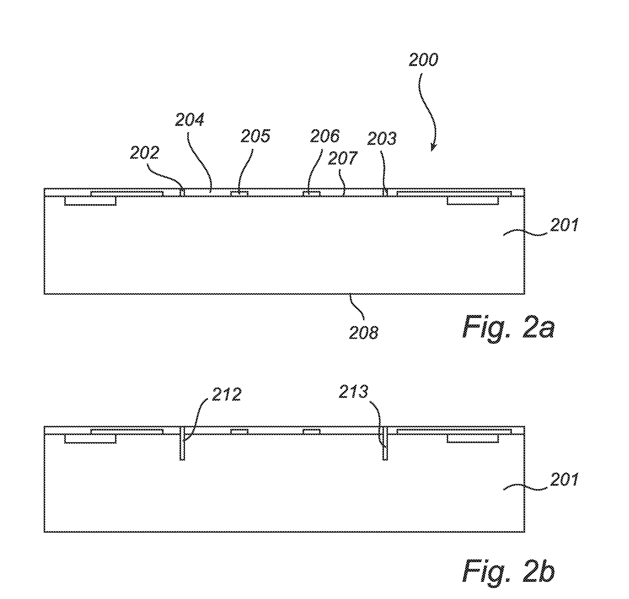
[0060]FIG. 2 illustrates schematically the steps a) to h) over the process of constructing an electronic device according to one aspect of the invention. Sections a) to h) of FIG. 2 depicts an electronic device 200 in which the invention is implemented, although various other embodiments are possible as known to a person skilled in the art. The device 200 comprises a substrate 201 of a semiconductor material of type N or P. Typically, the substrate 201 have been prepared using standard processes such as doping, diffusion, etchin...


PUM

PropertyMeasurementUnit
Depthaaaaaaaaaa
Depthaaaaaaaaaa
Thicknessaaaaaaaaaa

Abstract

The present invention relates to an electronic device for providing improved heat transporting capability for protecting heat sensitive electronics and a method for producing the same. The present invention also relates to uses of the electronic device for various applications such as in LED lamps for signalizing, signage, automative and illumination applications or a display apparatus or any combinations thereof.

Description

TECHNICAL FIELD[0001]The present invention relates to an electronic device providing improved heat transporting capability for protecting heat sensitive electronics and a method for producing the same. The present invention also relates to uses of the electronic device for various applications.BACKGROUND OF THE INVENTION[0002]Electronic devices comprise a growing number of electronic components, some of which generate large amount of excess heat and some of which are more sensitive to heat, causing the electronics to malfunction, sometimes temporary and sometimes permanently.[0003]This has become a growing concern in the electronics industry, especially with the ongoing development of smaller and smaller electronic devices concurrent with the increasing number of electronic elements on a given area. Consequently, it has become increasingly difficult to eliminate unwanted influence between these components, such as for instance due to heat emission. In the process of finding a remedy...

Claims


Application Information

Patent Timeline
IPC IPC(8): H02H9/04H05K7/20C25D5/02C23F1/00B23K31/02H01L33/64
CPCF21V29/004F21Y2101/02H01L2224/16H01L25/167H01L33/642H01L23/3677F21Y2115/10F21V29/70
Inventor FERRU, GILLES
Owner NXP BV
Learn More