Apparatus and Methods for High-Performance Liquid Cooling of Multiple Chips with Disparate Cooling Requirements

a multi-chip, liquid cooling technology, applied in the direction of electrical apparatus casing/cabinet/drawer, instrument, etc., can solve the problems of increasing power density, increasing system performance limitations, and increasing the problem of effective heat removal, so as to reduce mechanical stresses in thermal bonds and effectively conduct heat

a multi-chip, liquid cooling technology, applied in the direction of electrical apparatus casing/cabinet/drawer, instrument, etc., can solve the problems of increasing power density, increasing system performance limitations, and increasing the problem of effective heat removal, so as to reduce mechanical stresses in thermal bonds and effectively conduct heat

US20090284921A1Inactive Publication Date: 2009-11-19IBM CORP

Image

  • Apparatus and Methods for High-Performance Liquid Cooling of Multiple Chips with Disparate Cooling Requirements
  • Apparatus and Methods for High-Performance Liquid Cooling of Multiple Chips with Disparate Cooling Requirements
  • Apparatus and Methods for High-Performance Liquid Cooling of Multiple Chips with Disparate Cooling Requirements

Examples


Embodiment Construction

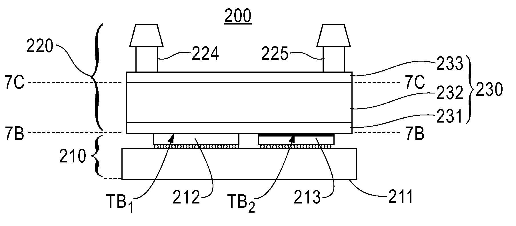
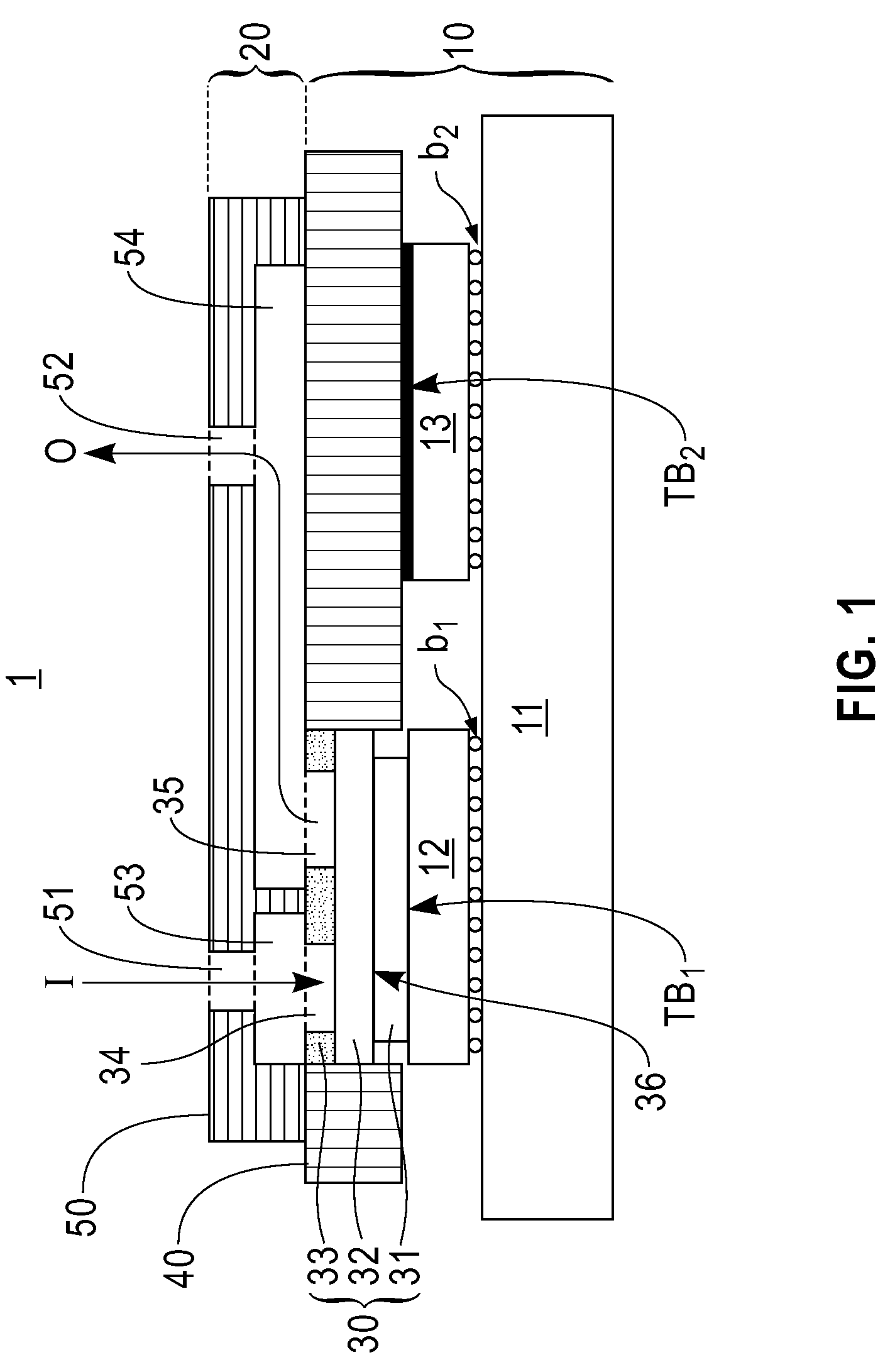
[0033]FIG. 1 is a schematic cross-sectional view of an electronic module according to an exemplary embodiment of the invention, which provides high-performance liquid cooling of a multi-chip module having multiple IC chips with disparate cooling requirements mounted face down on a common carrier. More specifically, FIG. 1 schematically illustrates an electronic module (1) comprising an IC chip module (10) with a plurality of IC chips (12) and (13) mounted face down on a multi-chip carrier (11), and a common liquid cooling module (20) (or cooling apparatus) that is thermally coupled to the non-active surfaces of the IC chips (12) and (13).

[0034]The chip module (10) may be a dual chip module (DCM) or multi-chip module (MCM), for example, where the IC chips (12) and (13) are mounted on the top surface of the chip carrier, which contains high density wiring, (11) arrays of fine pitch solder balls, such as C4s, (b1) and (b2) (˜0.15 mm pitch). The chip carrier (11) may be a first level pa...


PUM


Abstract

Apparatus and methods are provided for packaging multi-chip modules with liquid cooling modules designed to provide different thermal resistances for effectively conducting heat from various chips with disparate cooling requirements while minimizing mechanical stresses in thermal bonds due to thermal excursions.

Description

BACKGROUND[0001]1. Technical Field[0002]The present invention relates generally to apparatus and methods for high-performance cooling of multi-chip package structures having multiple chips with disparate cooling requirements mounted on a common substrate. More specifically, the present invention relates to apparatus and methods for packaging multi-chip modules with liquid cooling modules designed to provide different thermal resistances needed for effectively conducting heat from various chips with disparate cooling requirements while minimizing mechanical stresses in thermal bonds due to thermal excursions.[0003]2. Discussion of Related Art[0004]In the design and manufacture of semiconductor IC (integrated circuit) chip packages and modules (e.g., SCM (single chip modules) or MCMs (multi-chip modules)), it is imperative to implement mechanisms that can effectively remove heat generated by IC chip devices (such as microprocessors) to ensure continued reliable operation of the device...

Claims


Application Information

Patent Timeline
19 Nov 2009
Publication
US20090284921A1
IPC
H05K7/20
CPC
F28F3/086; F28F3/12; F28F2260/02; H01L23/473; H01L2224/16; H01L2924/10253; H01L2224/73253; H01L2924/09701
Inventors
COLGAN, EVAN GEORGE; GAYNES, MICHAEL ANTHONY