Self-Biased Phase Locked Loop

a phase locking loop and self-biased technology, applied in the direction of electrical equipment, pulse automatic control, etc., can solve the problems of difficult design of a self-biased pll satisfying all the requirements, capacitors of filter capacitors cannot be largely manufactured in size, bandwidth may be restricted, etc., to achieve easy implementation, reduce power supply noise, and simplify the circuit structure of the self-biased pll

Active Publication Date: 2009-11-26
SEMICON MFG INT (SHANGHAI) CORP
View PDF5 Cites 8 Cited by
  • Summary
  • Abstract
  • Description
  • Claims
  • Application Information

AI Technical Summary

Benefits of technology

[0032]Because the complex bias generator circuit is omitted, the circuit structure of the self-biased PLL is further simplified. Moreover, because the circuit structures of the LF, VCO and the bias current generator are simple, they are easy to be implemented.
[0033]The circuit of VCO may restrain the power supply noise. The power supply noise may affect the oscillation voltage. If the noise of the oscillation voltage is small, the frequency of the output signal of the VCO is stable and has a low jitter. Thus, the phase noise of the PLL is also small.
[0034]The loop bandwidth of the PLL is optimized. The loop bandwidth will not be too narrow when the input frequency is low and the loop bandwidth will not be too wide when the input frequency is high. Thus, the low frequency noise at the input terminal and the high frequency noise from the VCO can be restrained as far as possible.

Problems solved by technology

However, it may be difficult to design a PLL satisfying all the requirements.
On the other hand, the capacitor of the filter can not be manufactured largely in size due to the requirement of monolithic integration, and at the same time, the bandwidth may be restricted by the loop stability condition.
These restrictive conditions may result in the designed PLL with a narrow operation band and poor jitter performance.
The circuit structure of the bias generator is complex.
Therefore, in order to meet the requirement that the damping factor of the loop needs to be kept as a fixed value, a large modification is made to the basic PLL to construct the existing self-biased PLL and the structure of the existing self-biased PLL is complex.

Method used


Image

  • Self-Biased Phase Locked Loop
  • Self-Biased Phase Locked Loop
  • Self-Biased Phase Locked Loop

Examples


Embodiment Construction

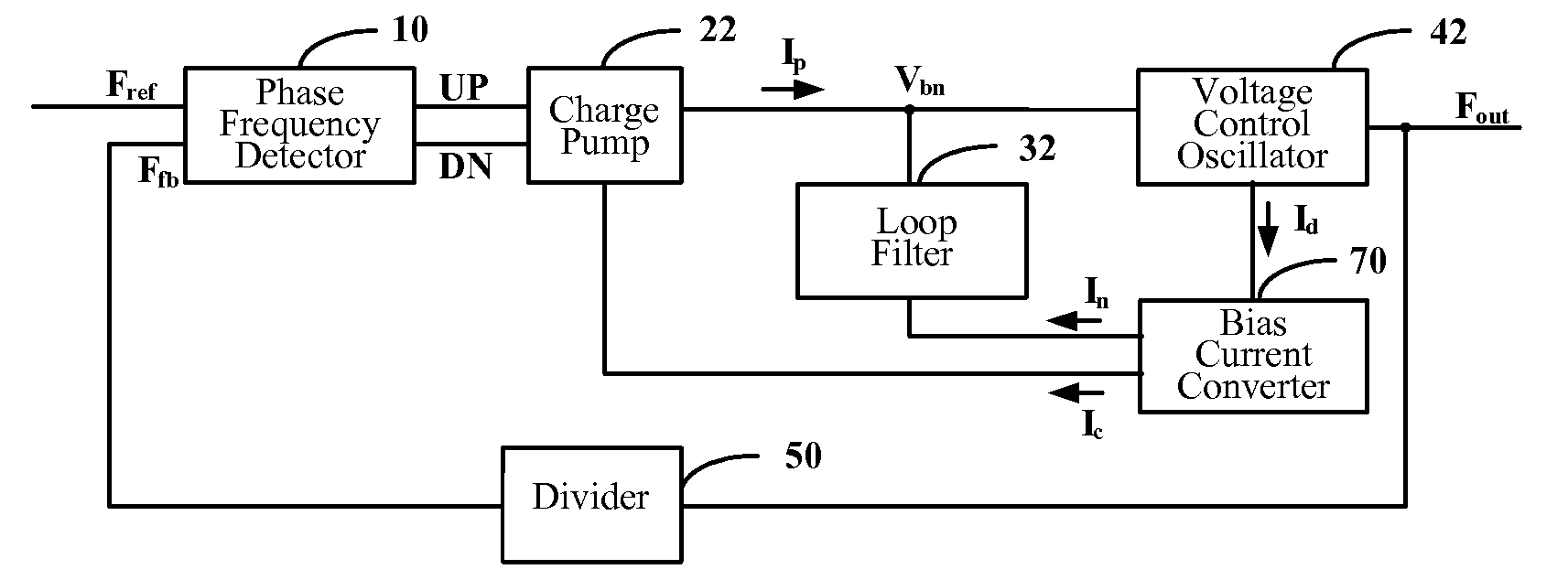
[0042]In embodiments of the present invention, a relationship between a resistor of a LF (that is, RP in Equation (1)) and a frequency division factor of a divider and a bias current output from a VCO and a relationship between a charging or discharging current output from a CP (that is IP in Equation (1)) and the bias current output from the VCO are established to eliminate the frequency division factor and the bias current so as to satisfy the requirement that the loop damping factor of the self-biased PLL needs to be kept as a fixed value.

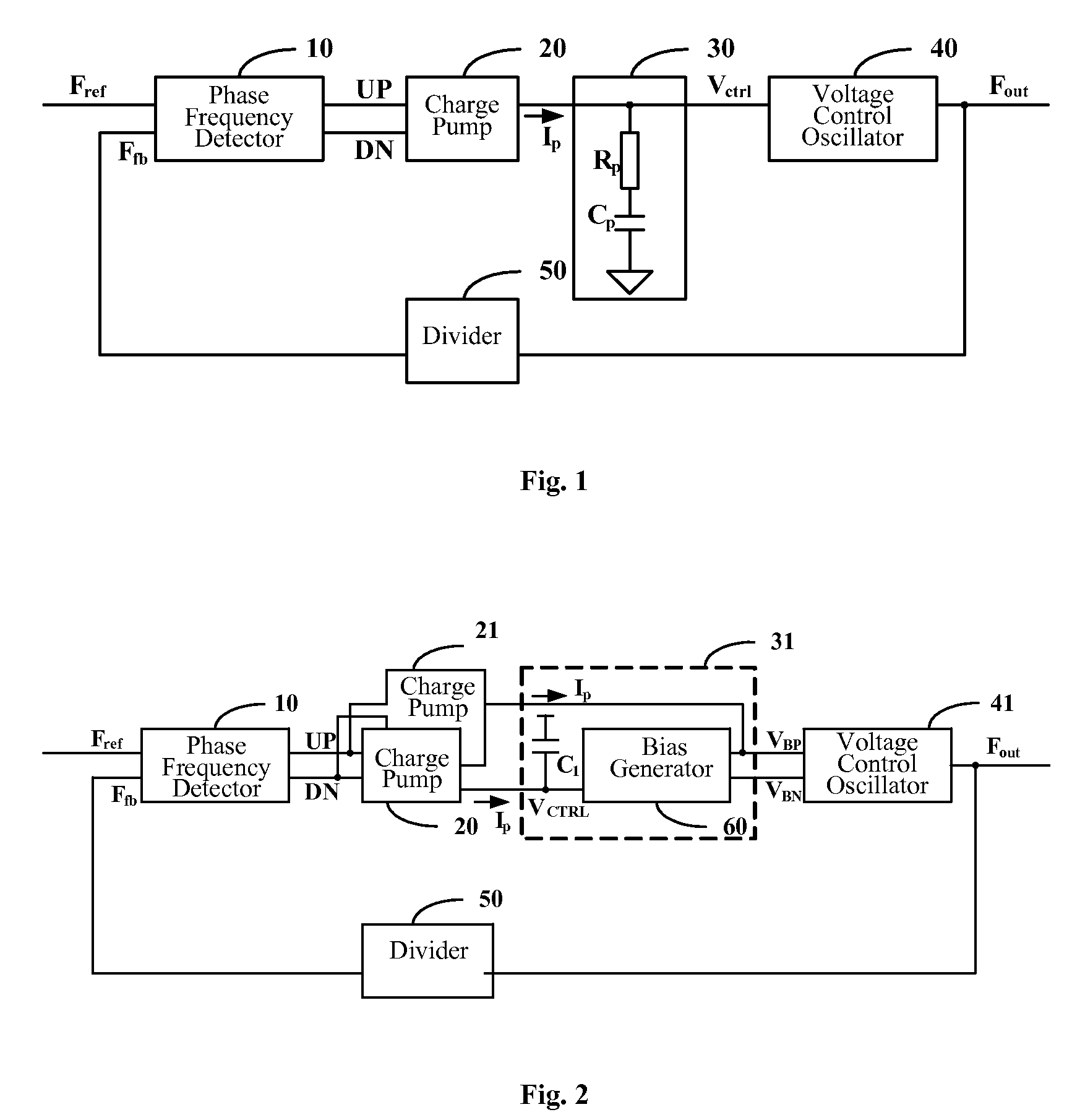
[0043]The embodiments of the present invention will be described in detail below with reference to the drawings. FIG. 5 is a schematic diagram of a basic structure of a self-biased PLL according to an embodiment of the present invention, and the self-biased PLL includes a PFD 10, a CP 22, an LF 32, a VCO 42, a bias current converter 70 and a divider 50.

[0044]The PFD 10 detects a frequency difference and a phase difference between an input signal...


PUM


Abstract

The present invention discloses a self-bias PLL including a phase frequency detector, a charge pump, a loop filter, a voltage control oscillator, a divider and a bias current converter. A charging or discharging current output from the charge pump equals to a first control current. A resistor of the loop filter is controlled by a first control voltage a second control voltage which is adjusted according to the first control voltage and a second control current. The loop filter increases or decreases the first control voltage according to the charging or discharging current output from the charge pump. The voltage control oscillator generates a bias current and an oscillation voltage according to the first control voltage and increases or decreases an oscillation frequency according to the increase or decrease of the oscillation voltage. The circuit structure of the self-bias PLL is simple and the self-bias PLL has a low jitter.

Description

FIELD OF THE INVENTION[0001]The present invention relates to the field of phase locked loop, and in particular to a self-biased phase locked loop.BACKGROUND OF THE INVENTION[0002]A Phase Locked Loop (PLL) is widely applied in a System on Chip (SOC) to constitute a frequency synthesizer, a clock generator and the like. FIG. 1 is a basic structure of a PLL, in which a Phase Frequency Detector (PFD) 10 detects a frequency difference and a phase difference between an input signal Fref and a feedback signal Ffb, and generates pulse control signals UP and DN and sends them to a Charge Pump (CP) 20. In the CP 20, the pulse control signals UP and DN are converted into a current IP so as to charge or discharge a capacitor CP in a Loop Filter (LP) 30, the LP 30 generates and sends a control voltage Vctrl to a Voltage Control Oscillator (VCO) 40. The VCO 40 increases an oscillation frequency as the control voltage Vctrl is boosted, and the VCO 40 decreases the oscillation frequency as the cont...

Claims


Application Information

Patent Timeline
Patent Type & Authority Applications(United States)
IPC IPC(8): H03L7/00
CPCH03L7/0895H03L7/0995H03L7/093H03L7/0898
Inventor FU, ZHIGANG
Owner SEMICON MFG INT (SHANGHAI) CORP
Why Eureka
Try Eureka