Vacuum chamber

a vacuum chamber and vacuum technology, applied in the field of vacuum chambers, can solve the problems of unsatisfactory effects, ceramic chambers also have certain problems, increase the size, cost and power consumption of magnets required to provide the field, etc., to reduce the level of inductive heating and consequent risk of components melting, reduce the risk of contamination of the vacuum, and reduce the production of eddy currents

Inactive Publication Date: 2009-11-26
TESLA ENG
View PDF6 Cites 7 Cited by
  • Summary
  • Abstract
  • Description
  • Claims
  • Application Information

AI Technical Summary

Benefits of technology

[0051]The vacuum chambers of the present invention may be used in any desired application. As discussed above, the vacuum chambers are particularly suitable for use where the vacuum chamber is likely to be in the presence of a changing e.g. alternating magnetic field. The use of the electrically non-conducting layers for the walls may reduce the level of inductive heating, and consequent risk of components melting, and reduce the production of eddy currents which might otherwise distort the magnetic field in such a context.
[0052]In accordance with a further aspect of the invention, the present invention therefore provides a vacuum system comprising a vacuum chamber in accordance with the invention of any of its aspects or embodiments. In preferred embodiments the vacuum system further comprises means for applying a time varying e.g. alternating magnetic field to a charged particle beam within the vacuum chamber in use. For example, the means may be one or more magnets arranged to apply a time varying e.g. alternating magnetic field to the chamber. The magnets are prefera...

Problems solved by technology

This may result in undesirable effects such as inductive heating of the chamber walls occurring in use as a result of the production of eddy currents induced by the changing magnetic field, or attenuation of the magnetic field it is intended to produce.
However, the Applicant has realized that these ceramic chambers also have certain problems.
For example, ceramic chambers tend to be relatively thick walled in order to provide acceptable levels of vacuum performance, increasing the associated costs, space requirements and, when a magnetic field is to be applied to a charged particle beam in the chamber, increasing the size, cost and power consumption of the magnets required to provide the field.
Eddy currents are undesirable as, de...

Method used


Image

  • Vacuum chamber
  • Vacuum chamber
  • Vacuum chamber

Examples


Embodiment Construction

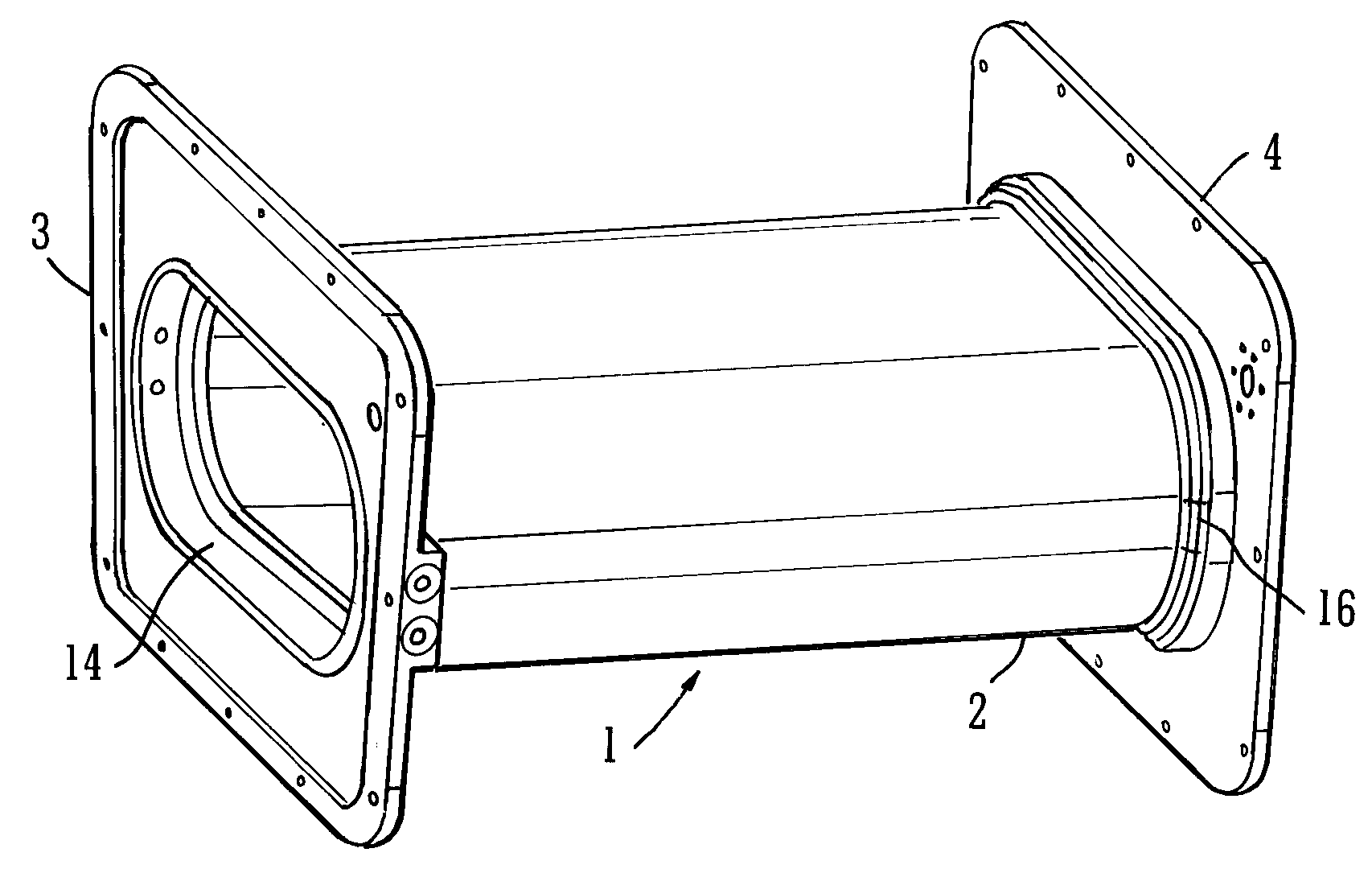
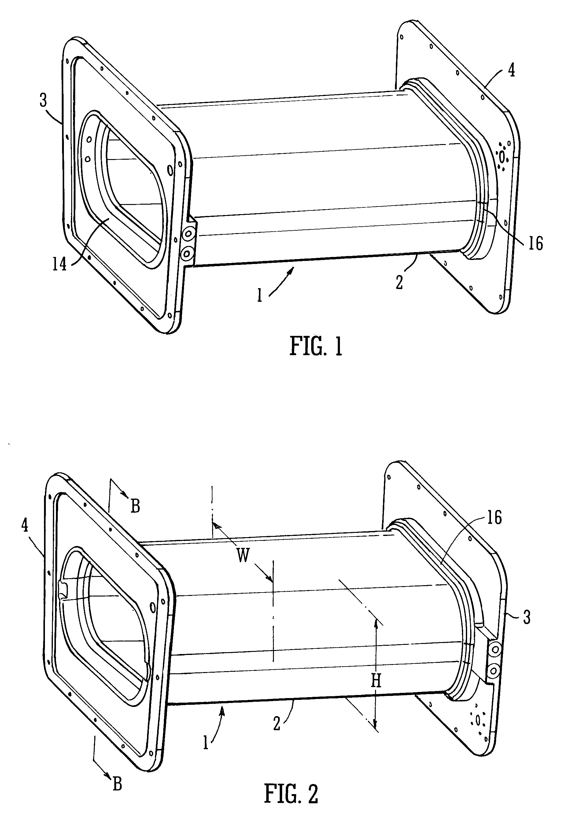
[0067]As may be seen most readily in FIGS. 1 and 2, the vacuum chamber 1 is rectangular in vertical cross section, and has side walls 2 extending between the ends thereof. At each end of the chamber there is a flange 3,4 respectively joined thereto for connecting the vacuum chamber 2 adjoining apparatus in a vacuum system.

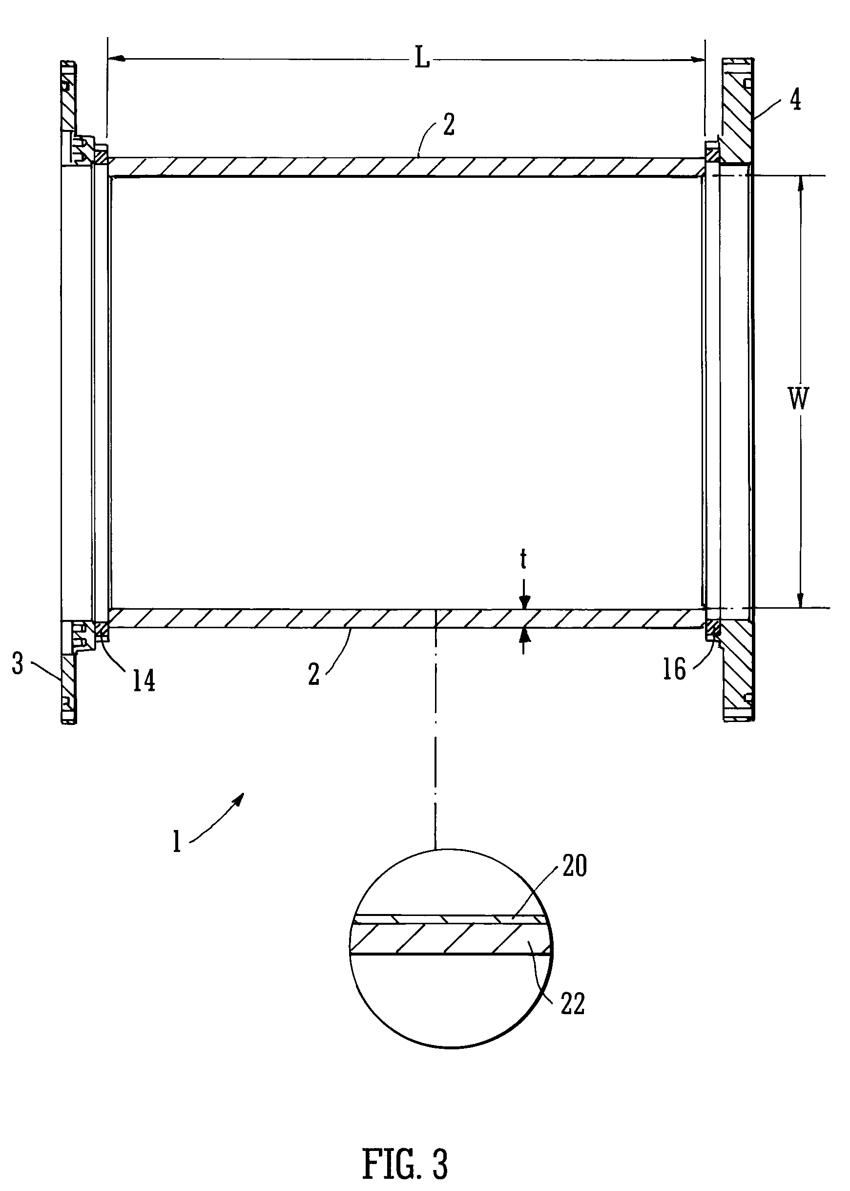
[0068]In the particular illustrated embodiment, the width W of the vacuum chamber exceeds its height. The width is around at least twice the height. The width W of the chamber measured between the internal surfaces of its walls along the line W of FIG. 3 is around 320 mm. The corresponding height of the vacuum chamber marked H in FIG. 4 is around 127 mm.

[0069]The walls of the cylinder have a thickness of around 2.125 mm. The thickness is marked t on FIGS. 3 and 4. The vacuum chamber has a length L of 45 cm. It will be appreciated that these dimensions are exemplary only, and the vacuum chamber may be of any dimensions suitable for an intended application. The prese...


PUM

PropertyMeasurementUnit
Thicknessaaaaaaaaaa
Thicknessaaaaaaaaaa
Magnetic fieldaaaaaaaaaa

Abstract

A vacuum chamber 2 has walls having an inner layer 20 of a gas impermeable electrically non-conductive material and an outer layer 22 of a different electrically non-conducting material. The inner layer 20 is a polymeric film layer of Kapton® polyimide. The outer layer 22 is a composite material which includes reinforcing carbon or glass fibers bound in a matrix of epoxy resin. The vacuum chamber has end flanges for attaching it to adjacent parts of a vacuum system. The vacuum chamber is made by placing a sheet of Kapton® material around a mould and sealing its ends together. The composite material is then wound onto the inner layer in its wet form to provide the outer layer. The outer layer material is then cured to dry the epoxy resin, binding the layer to the inner layer, and the multi-layer structure removed from the mould. The vacuum chamber is particularly suitable for use in an ion implantation system in the presence of a time varying magnetic field.

Description

BACKGROUND[0001]1. Field[0002]The present invention relates to vacuum chambers, vacuum systems comprising such chambers, and methods of using and manufacturing such vacuum chambers and systems.[0003]2. Description of the Related Art[0004]Vacuum chambers are commonly used in a wide range of vacuum applications. The Applicant has realized that known vacuum chambers have certain drawbacks, particularly in applications in which a charged particle beam is passed through the chamber in the presence of a time varying magnetic field. This may occur, for example, in semiconductor processing applications, such as ion implantation systems. For example, some conventional vacuum chambers exhibit relatively high levels of electrical conductivity. This may result in undesirable effects such as inductive heating of the chamber walls occurring in use as a result of the production of eddy currents induced by the changing magnetic field, or attenuation of the magnetic field it is intended to produce.[...

Claims


Application Information

Patent Timeline
IPC IPC(8): B01J19/00
CPCB29C70/086H05H7/14H01L21/6719B29C70/32
Inventor BEGG, MICHAEL COLINRAMAGE, JAMES CUMMING
Owner TESLA ENG
Why Eureka
Try Eureka