Tank with a gas supply and extraction device for storing cryogenic liquid or fuel for spacecraft

a technology of cryogenic liquid and extraction device, which is applied in the direction of liquid degasification, container discharging method, separation process, etc., can solve the problems of undesirable liquid ejection out of the gas extraction arrangement, high energy consumption, and relatively high cost, so as to improve reliability and robustness, the effect of reducing costs

Active Publication Date: 2009-12-03
AIRBUS DEFENCE & SPACE
View PDF58 Cites 8 Cited by
  • Summary
  • Abstract
  • Description
  • Claims
  • Application Information

AI Technical Summary

Benefits of technology

[0010]The above objects have been achieved according to the invention in a tank arrangement for storing cryogenic or non-cryogenic liquids such as storable fuels for the operation of spacecraft, and a pressurized driving gas serving as a conveying medium for driving the liquid out of the tank. The tank comprises a tank shell that bounds a tank interior space therein, and that comprises a tank wall with a tank opening as well as a tank lid that closes or covers the tank opening. The arrangement further includes at least one gas supply and extraction device comprising a refillable reservoir that is arranged in the tank and that uses baffles or capillary plates and screens or sieves under the effect of surface tension to separate the gas from the liquid. Particularly according to the invention in such a tank arrangement, the gas supply and extraction device is preferably arranged in the upper portion of the tank, for example in the upper half of the tank, and includes a device housing that is preferably essentially cylindrical. The device and especially the device housing is arranged directly on and connected directly to the tank shell, e.g. preferably the tank lid, at the upper portion of the tank. The gas extraction device further includes a plurality of passage bodies that are arranged on the perimeter of the device housing near a first end (e.g. the upper end) thereof, and at least one additional passage body that is arranged at the opposite second end of the device housing. The passage bodies provide respective passage openings which flare so that the openings enlarge outwardly away from the device toward the interior of the tank. The passage bodies are thus preferably trumpet shaped. The device further includes a gas conduit that leads from the inside of the device housing out from the tank to an outlet, and preferably to at least one gas consumer, e.g. a thruster nozzle, of the spacecraft. The passage bodies providing the expanding openings are each respectively equipped with plates, preferably metal plates, that protrude into the opening from the inner wall of the passage body successively on opposite alternating sides of the passage body. The opening of each passage body preferably communicates through a double screen or sieve sleeve with the interior of the device housing. Furthermore, capillary plates extending parallel to the longitudinal axis of the housing are arranged on the inner wall of the device housing. The device housing, the passage bodies and the various different plates, as well as the tank shell, are preferably made of metal, but other materials such as fiber reinforced composites or plastics are also suitable depending on the particular application. A respective baffle plate is preferably arranged in the tank interior space in front of the outer flared opening of each respective passage body, and the baffle plate of the passage body at the second end of the device housing has at least one hole passing therethrough.
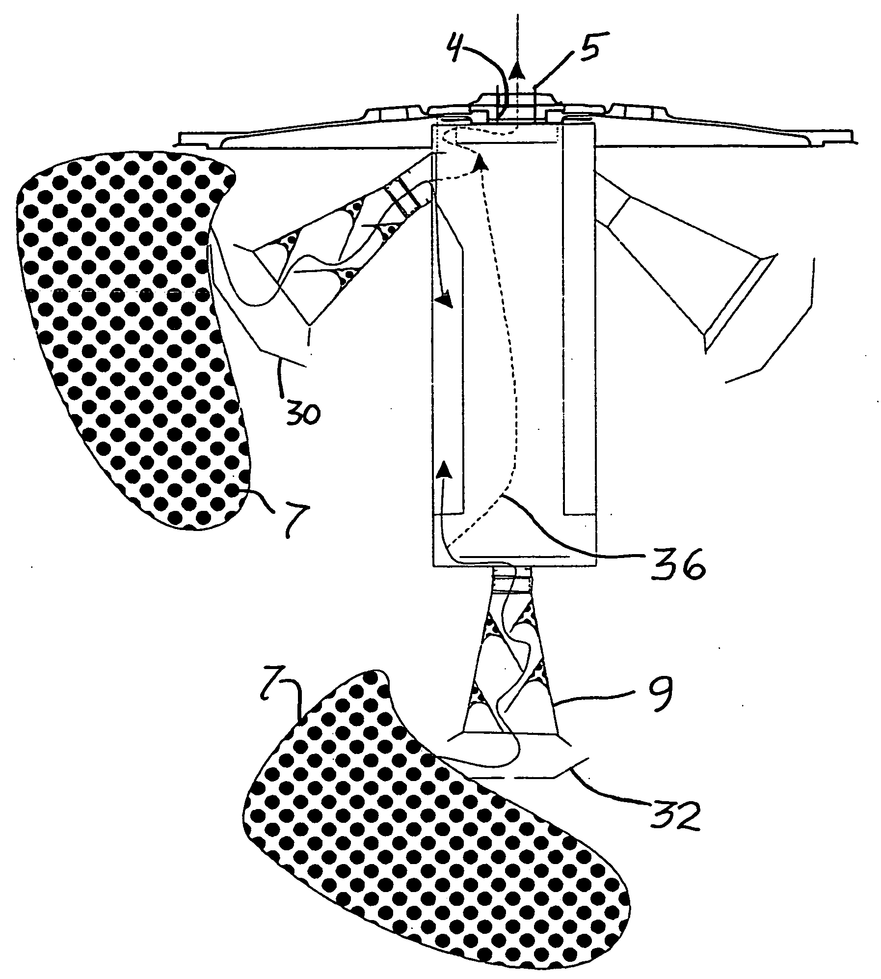
[0011]The penetration of liquids into the opening of the trumpet-shaped passage body is substantially prevented by the arrangement of successive capillary plates protruding alternately from opposite sides of the passage body inner wall into the opening of the passage body. The double screen sleeve and a further wetting barrier leading from the passage body into the interior of the device housing further serve to block the passage of liquid in a preferred embodiment as will be discussed below. Nonetheless, if liquid does penetrate into the interior of the gas supply and extraction device housing, for example due to larger liquid movements, then the penetrating liquid will be captured and guided away by the capillary plates in the interior of the reservoir and will thereby be separated from the gas.
[0012]Thus, the gas supply and extraction device provided in the tank arrangement according to the invention has the advantage, with the installed fixed mechanical capillary plates and screens, that it consists of only passive components, i.e. does not require or use any active components, for example does not comprise any active valves, to carry out the separation of gas from liquid. Therefore, the entire system does not require any additional or separate controller for controlling the gas extraction device, but rather the separation of the gas from the liquid occurs passively by the fixed mechanical components. This is a significant advantage over gas separation systems that use active components and require a specialized control, for example systems that require a pre-acceleration for separating the liquid from the gas, or that achieve a phase separation using active control of valves or using an additional heating and vaporization of the fuel. Therefore, the tank arrangement according to the invention is characterized by a considerably simplified construction, an increased reliability and robustness, and reduced costs, in comparison to 
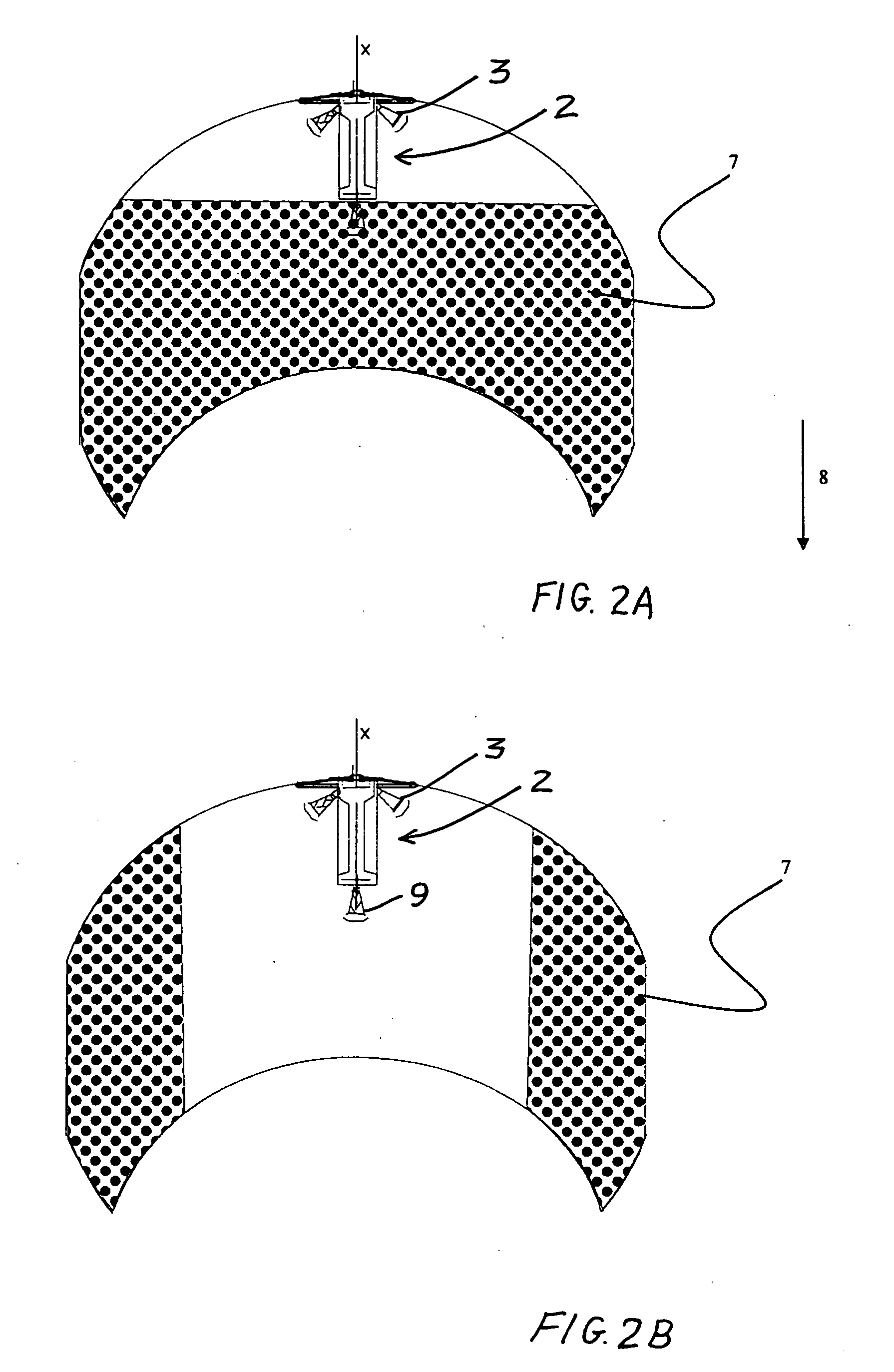
active systems, and further ensures the liquid-free extraction of gas out of the tank arrangement during phases of reduced acceleration, such as weightless phases or ballistic flight phases, as well as during accelerated flight phases as they arise in connection with the upper stages of rockets and transfer vehicles in space flight.
[0013]It is a special feature of the tank according to the present invention, that it is equipped with a gas supply and extraction device in which the bottom area of the device housing has only one trumpet-shaped or flaring passage body that forms a corresponding flaring opening. More particularly, a single trumpet-shaped passage body that defines a flaring opening is provided centered axially on the lengthwise axis of the housing, on the bottom wall or floor of the housing, of the gas supply and extraction device. Additional trumpet-shaped passage bodies are provided in the upper area of the device housing. This provides an especially simple construction of the gas supply and extraction device, and also achieves an optimum ease and adaptability of the installation thereof, and also optimizes the weight, and the later inspection and maintenance or replacement thereof. The latter is especially an important aspect of the inventive apparatus for application in reusable spacecraft or spaceflight systems, to which the tank according to the invention is especially well suited.
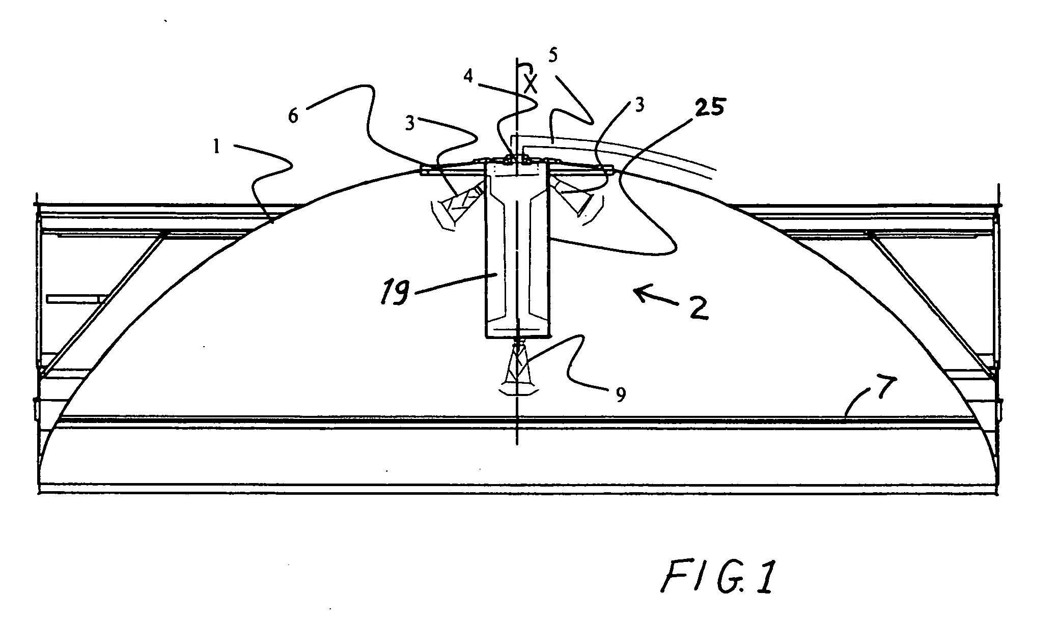
[0014]A further advantage of the inventive tank arrangement is that it achieves a very good thermal connection and heat transfer junction between the gas supply and extraction device and the tank shell or wall structure of the tank. To achieve this, preferably the gas supply and extraction device is directly mounted on or directly connected to the tank lid that covers a tank opening in the area of the upper tank dome where the driving gas predominantly accumulates. In this area of the upper tank dome, the temperature is especially high relative to the temperature of the cryogenic liquid fuel stored in the tank, and the tank shell becomes heated (relative to the cryogenic liquid fuel) especially well by heat introduction (e.g. thermal conduction) into the tank. Because the gas supply and extraction device, according to the invention, is directly structurally and thermally connected with the tank lid, this arrangement of the gas supply and extraction device additionally performs as a heat exchanger in the gas outlet area of the tank shell. Thus, the inventive gas supply and extraction device additionally serves to ensure more-constant temperature conditions, especially when the pressurized driving gas (and / or fuel vapor) in the tank quickly cools-off during a pressure release from the tank through the gas supply and extraction device. Among other things, this especially has a positive influence on position regulating systems, e.g. thrusters that are operated or driven with the pressurized gas. This effect is especially strong in applications with cryogenic fuels, of which the gas temperature generally increases considerably along with the separation of the gas from the liquid phase.
[0015]Still further, the inventive direct mounting or connection of the gas supply and extraction device on the tank lid of the tank also provides the advantages of easier installation, maintenance, repair, or replacement of the gas supply and extraction device, and also the advantage that in this manner the gas supply and extraction device can be installed in the tank at a later point in time. This allows the gas supply and extraction device to be later retrofitted onto existing tanks without significant modifications, and also simplifies the tank verification and approval process. Namely, the necessary verification tests, for example such as vibration tests to prove the structural strength, integrity and reliability of the arrangement, can thus be carried out on a sub-component comprising the gas supply and extraction device together with the tank lid on which it is mounted, in that merely the tank lid with the gas supply and extraction device mounted thereon simply needs to be clamped into the testing system and vibrated to carry out the vibration test. These tests conducted at the component level are much simpler and therefore achieve a considerable cost savings in comparison to systems in which the structural integrity of the entire complete tank arrangement including any gas supply and extraction system arranged in the tank must be tested and verified as a whole, i.e. as a complete tank system rather than on a sub-component basis.

Problems solved by technology

This problematic situation especially arises in cryogenic liquid storage systems for space travel vehicles that must operate over a long time span in orbit in a weightless condition.
Moreover, the ejection of liquid out of the gas extraction arrangement is undesirable insofar as the liquid fuel is then no longer available for fueling the main rocket engine of the spacecraft.
However, this method requires a high amount of energy for vaporizing the liquid fuel.
This method, however, requires an active directed acceleration of the spacecraft by means of an additional propulsion system, which is generally relatively costly and complicates the operation of the spacecraft.
This latter known system is provided for use in connection with fuel cells and is not suitable for separation of cryogenic liquids from gases.
Further apparatuses known from U.S. Pat. No. 4,435,196 and U.S. Pat. No. 4,617,031 are limited to use in the gravitational field of earth, and are thus not suitable for separating cryogenic liquids from gases in tanks in spacecraft.

Method used


Image

  • Tank with a gas supply and extraction device for storing cryogenic liquid or fuel for spacecraft
  • Tank with a gas supply and extraction device for storing cryogenic liquid or fuel for spacecraft
  • Tank with a gas supply and extraction device for storing cryogenic liquid or fuel for spacecraft

Examples


Embodiment Construction

[0030]FIG. 1 schematically shows an upper portion of an upper stage fuel tank with a curved shape, as typically used in an upper stage of a spacecraft. The fuel tank arrangement includes a tank shell 1 enclosing the interior tank space of the tank, as well as a gas supply and extraction device 2 arranged in the upper portion of the tank shell 1. The tank shell 1 includes a tank wall and a tank lid 6 that covers or closes an opening in the tank wall. The tank wall and the tank lid 6 may be made of metal, plastic, composite material, or other known suitable material.

[0031]Throughout this application, the “upper” portion of the tank or of the gas supply and extraction device 2, for example, refers to the portion oriented away from the thrust outlet of the main rocket engine or a thruster of the spacecraft (which is not shown), i.e. in the direction of the thrust produced by a main rocket engine or a thruster of the spacecraft. References to directions such as “up” and “down”, or “upper...


PUM

PropertyMeasurementUnit
perimeteraaaaaaaaaa
areaaaaaaaaaaa
thermally conductingaaaaaaaaaa

Abstract

A gas supply and extraction device is arranged preferably on a tank lid or a tank wall in a tank for storing a pressurized driving gas and a liquid such as fuel or oxidizer for operation of a spacecraft. A device housing defines an interior reservoir space. Upper trumpet-shaped passage bodies and a lower trumpet-shaped passage body communicate from the interior reservoir space into the interior space of the tank. By capillary effects, baffle plates, deflector plates, capillary plates, a separation chamber and other components separate liquid from gas entering the device, so that the gas can be extracted while the liquid is stored in the reservoir space of the device until it is drained back into the tank during an accelerated operation phase of the spacecraft.

Description

CROSS REFERENCE TO RELATED APPLICATION[0001]The present application is related to U.S. application Ser. 12 / 012,640 filed on Feb. 4, 2008 by the same inventors as the present application, and published as US 2008 / 0237099 on Oct. 2, 2008. The entire disclosure of the earlier related application is incorporated herein by reference.PRIORITY CLAIM[0002]This application is based on and claims the priority under 35 U.S.C. §119 of German Patent Application 10 2008 026 320.6, filed on Jun. 3, 2008, the entire disclosure of which is incorporated herein by reference.FIELD OF THE INVENTION[0003]The invention relates to a tank for storing a cryogenic liquid or a liquid fuel for the operation of a spacecraft, wherein a pressurized driving gas serves to drive the liquid or fuel out of the tank, and wherein the tank is fitted with a gas supply and extraction device that uses surface tension to separate the driving gas from the liquid.BACKGROUND INFORMATION[0004]Tanks of the above mentioned type are...

Claims


Application Information

Patent Timeline
Patent Type & Authority Applications(United States)
IPC IPC(8): B01D19/00F17C1/00
CPCB64G1/402Y02E60/321F17C2201/0104F17C2201/0128F17C2201/0157F17C2205/0302F17C2205/0397F17C2221/011F17C2221/012F17C2221/08F17C2223/0161F17C2227/0192F17C2227/0302F17C2227/0379F17C2260/011F17C2260/012F17C2260/027F17C2270/0194F17C2270/0197F17C13/088Y02E60/32
Inventor BEHRUZI, KEI PHILIPPNETTER, GASTON
Owner AIRBUS DEFENCE & SPACE
Why Eureka
Try Eureka