Biomass Combustion Chamber and Refractory Components

a combustion chamber and biomass technology, applied in the field of biomass combustion chambers and refractory components, can solve the problems that the chambers themselves can affect the thermal and combustion efficiency of the load or fuel, and achieve the effects of improving the thermal and combustion efficiency of the biomass combustor, improving the efficiency of biomass combustion, and improving fuel utilization

Inactive Publication Date: 2009-12-03
FUJITSU LTD
View PDF14 Cites 13 Cited by
  • Summary
  • Abstract
  • Description
  • Claims
  • Application Information

AI Technical Summary

Benefits of technology

[0008]The present invention is an advance in utilizing material science technology to improve the thermal and combustion efficiency of a biomass combustor and the resultant work performed by heat transfer, for example, to process tubes. Radiative heat transfer is different from heat transfer by conduction or convection. Electromagnetic waves transmit the energy rather than a medium in radiative heat transfer. The properties of any material's surface tend to dominate eighty to ninety percent of that material performance in heat and combustion systems. The need to control air emissions and global warming while increasing the efficiency in biomass combustions is desirable. Improved fuel utilization and increased thermal output are desirable.

Problems solved by technology

The chambers themselves can impact the thermal and combustion efficiency of the load or fuel.

Method used


Image

  • Biomass Combustion Chamber and Refractory Components
  • Biomass Combustion Chamber and Refractory Components
  • Biomass Combustion Chamber and Refractory Components

Examples


Embodiment Construction

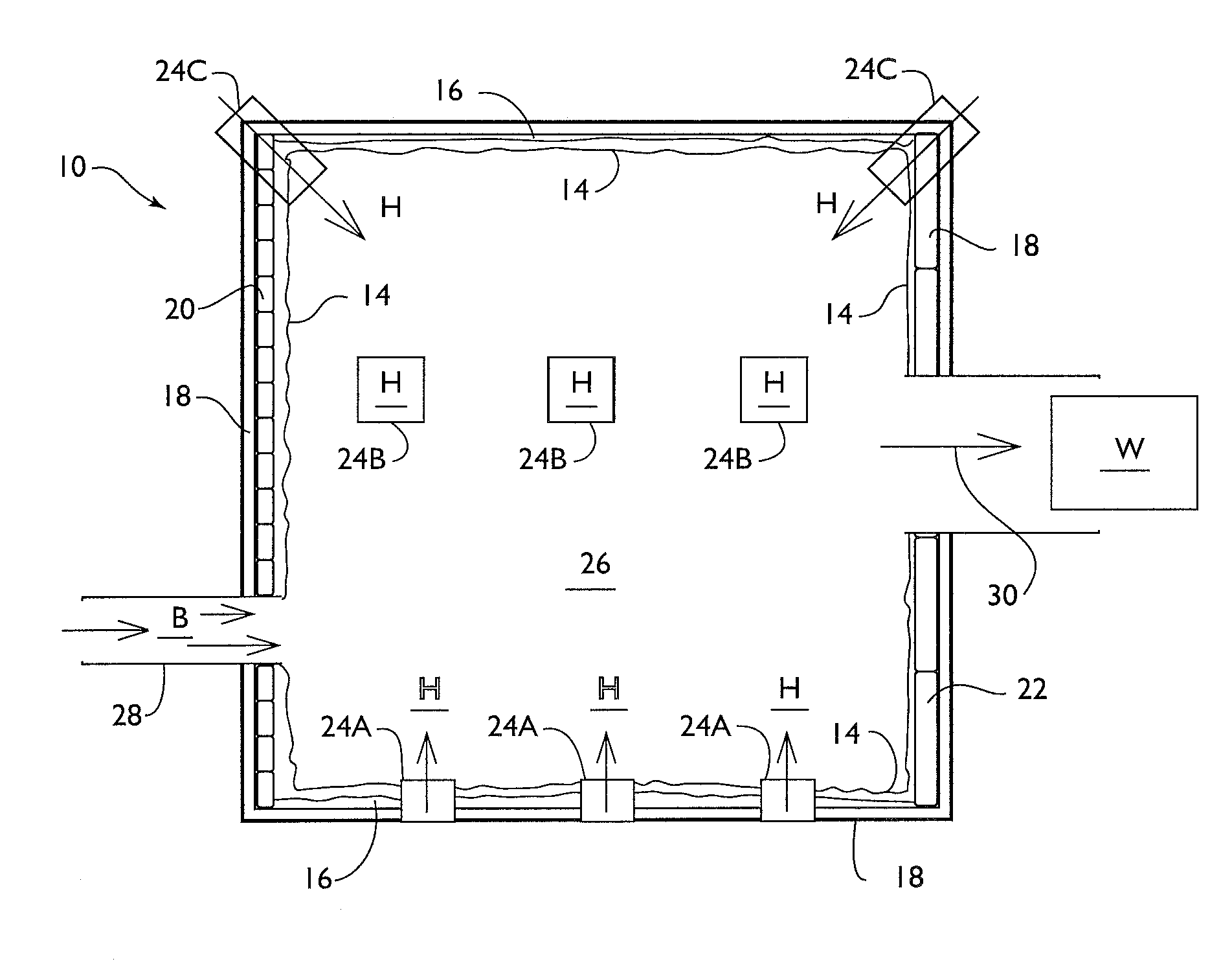
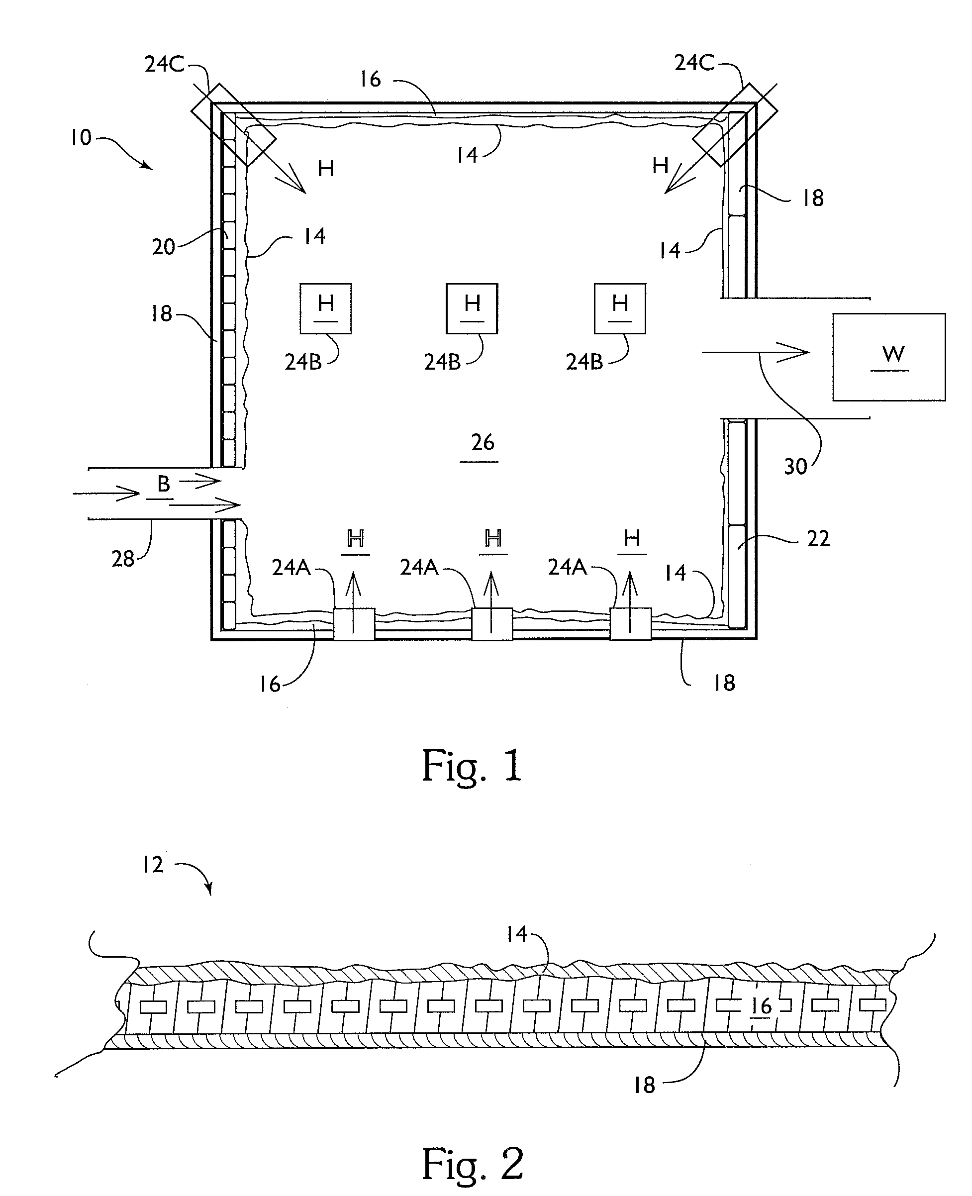
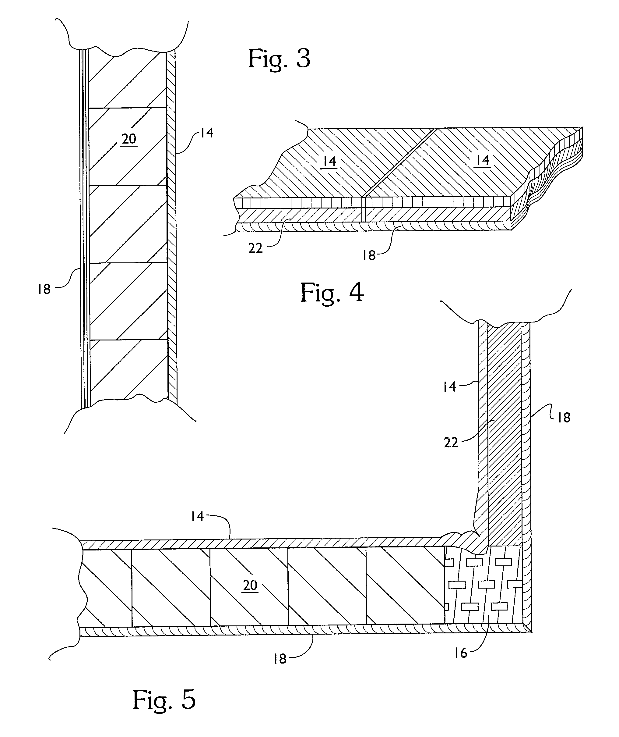
[0025]A thermal protective layer 14 may be disposed on at least a part or all of the exposed refractory surfaces of a biomass combustion chamber 10. A generic biomass combustion chamber 10 is depicted in FIG. 1. In some combustion chambers 10, at least part of the combustion chamber 10 wall 18 is composed of a plurality of refractory bricks 20, refractory board 22, or refractory castable 16, and combinations thereof, disposed therein forming an exposed surface of the chamber 10. In other combustion chambers, castable or ceramic fiber is used to form the refractory surface of the chamber 10, as is well known in the art. Ignition burners 24A-C may be provided alternatively, and in combination, in the floor 26 at 24B, in the sides of the chamber 10 at 24A, or in the corners at 24C to ignite the biomass and to provide a supply of gas, such as air, to facilitate the combustion of the biomass.

[0026]The biomass B is fed into the chamber 10 using a conventional inlet 28. Although multiple i...


PUM

PropertyMeasurementUnit
emissivityaaaaaaaaaa

Abstract

A combustion chamber has refractory walls, with an input feeding biomass into the chamber, and an ignition source to ignite the biomass. Each refractory wall component, refractory brick, panel or castable, has a surface exposed to heat generated within the chamber with a thermal protective layer consisting of a thermal enhancing high emissivity coating disposed on the exposed refractory surface. The coating contains from about 5% to about 35% of colloidal silica, colloidal alumina, or combinations thereof, from about 23% to about 79% of a filler, and from about 1% to about 20% of one or more emissivity agents.

Description

BACKGROUND OF THE INVENTION[0001]The combustion of biomass in the production of energy is increasing in response to increased pressures on other energy sources. The amount of radiation energy absorbed and reradiated from the biomass combustor walls occurs over a complete electromagnetic spectrum for radiative heat; hence, the combustor's thermal and combustion efficiency significantly improves if the emissivity and performance of the walls are changed. This is also true of the medium, such as for example process tubes, through which heat transfer takes place to perform the desired work, such as for example heating water / steam for use in facility heating systems, or in the generation of electricity.[0002]Refractories are classified as basic, high aluminum, silica, fireclay and insulating. Special refractories include silicon carbide graphite, zircon, zirconia, and fused cast, among others. Refractory lining may be formed of bricks, panels, castables, or thermal ceramic fiber to cover...

Claims


Application Information

Patent Timeline
Patent Type & Authority Applications(United States)
IPC IPC(8): F23M5/00B32B17/06B05D1/02
CPCC04B35/03
Inventor OLVER, JOHN W.
Owner FUJITSU LTD
Why Eureka
Try Eureka