Diffraction Gratings With Tunable Efficiency

Active Publication Date: 2009-12-03
NOKIA TECHNOLOGLES OY
View PDF4 Cites 61 Cited by
  • Summary
  • Abstract
  • Description
  • Claims
  • Application Information

AI Technical Summary

Benefits of technology

[0004]According to a first aspect of the invention, an optical device, comprises: a diffraction grating made of dielectric optical material with an index of refraction n and comprising a first surface with a structure having a structure height h and a structure period d, and a second surface; wherein the first surface is covered by hydrophobic material which reduces wettability of the diffraction grating for pre-selected liquids; a uniform liquid layer with the index of refraction k comprised of one of the pre-selected liquids, wherein the indexes of refraction n and k are substantially equal, the uniform liquid layer is disposed on the first surface of the diffraction grating, wherein parameters of the optical device are chosen such

Problems solved by technology

The display requires a large number of separate liquid droplets to be created and maintained rigidly in an array formation, which might not be possible in practical applications.
Also, light

Method used


Image

  • Diffraction Gratings With Tunable Efficiency
  • Diffraction Gratings With Tunable Efficiency
  • Diffraction Gratings With Tunable Efficiency

Examples


Example

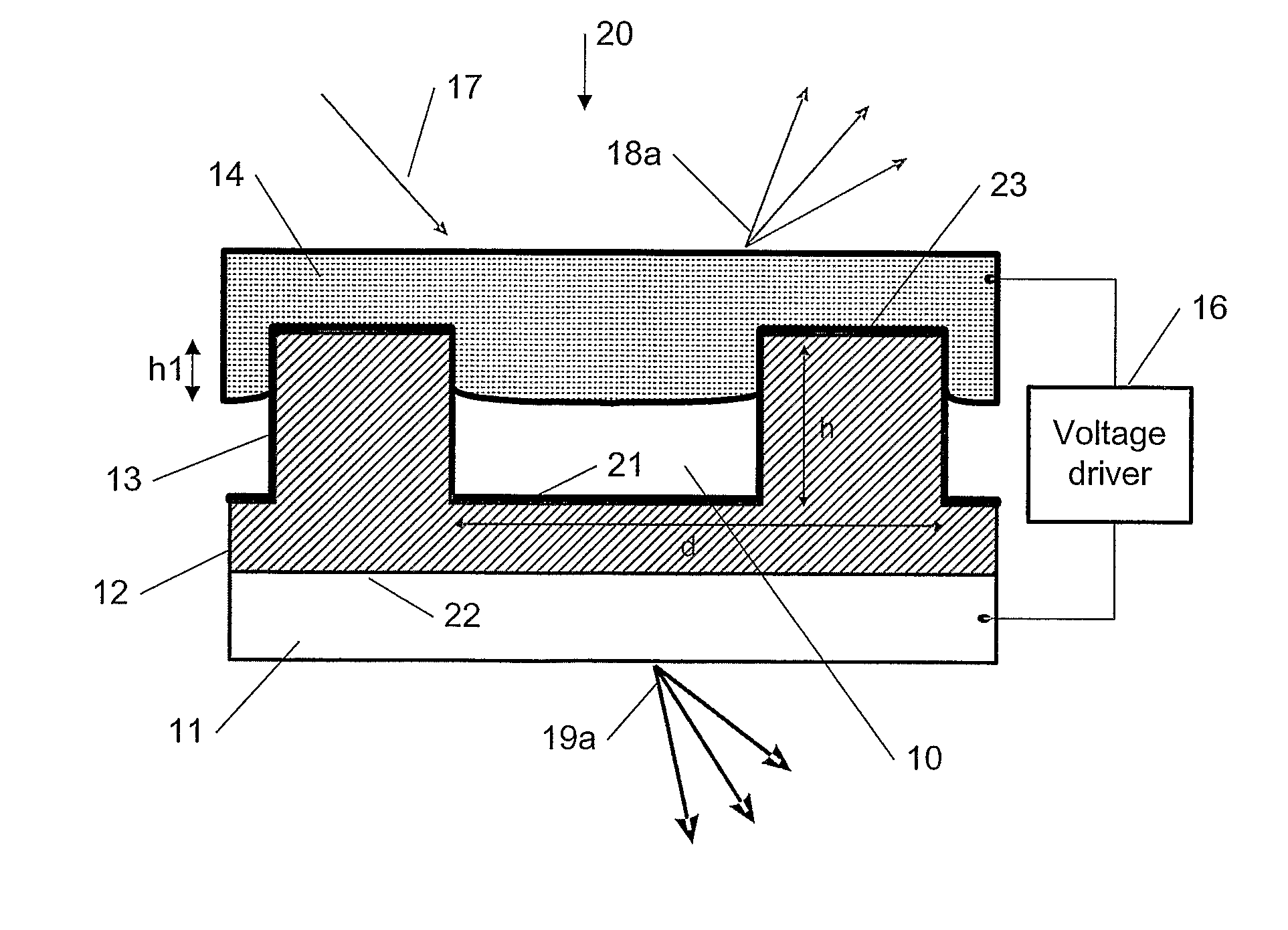
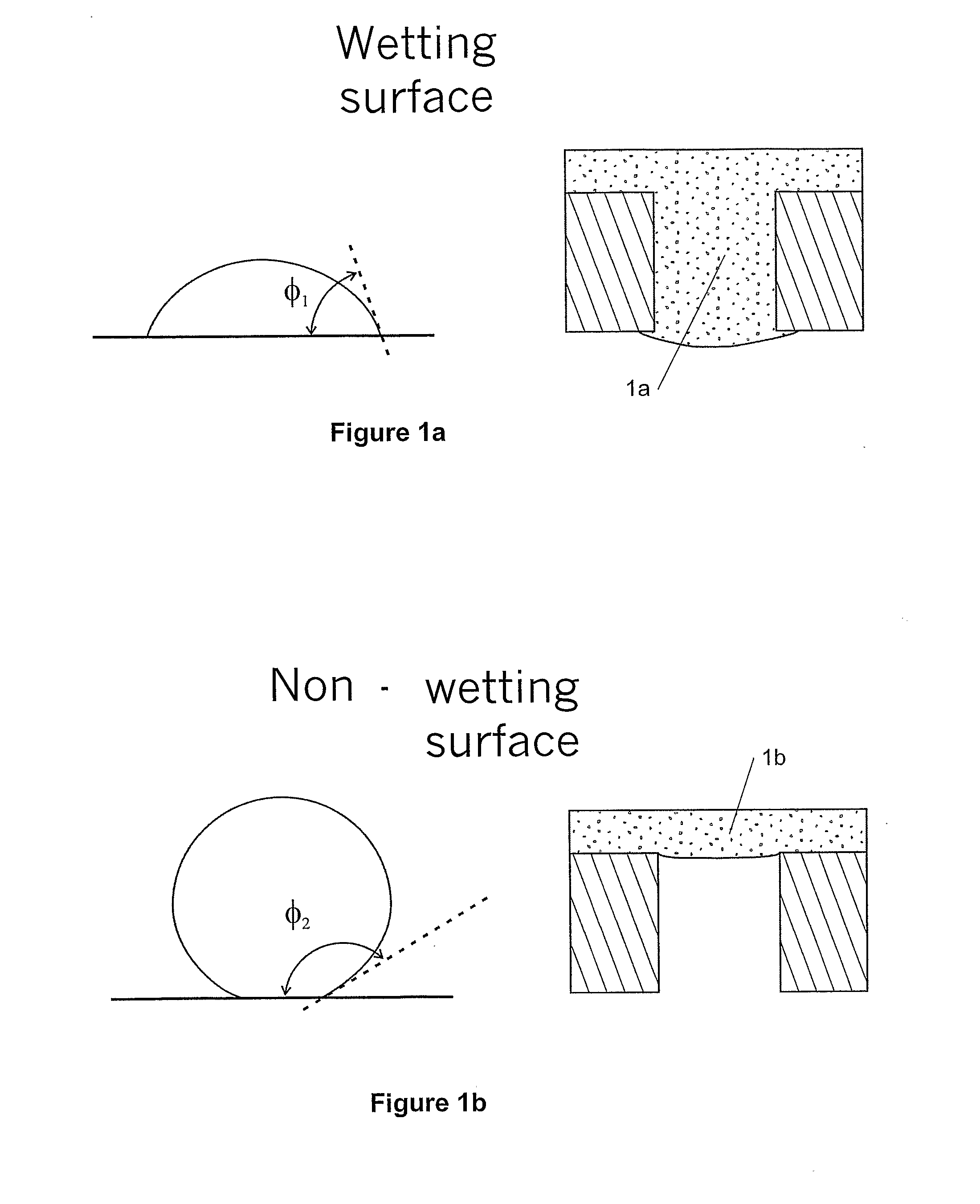
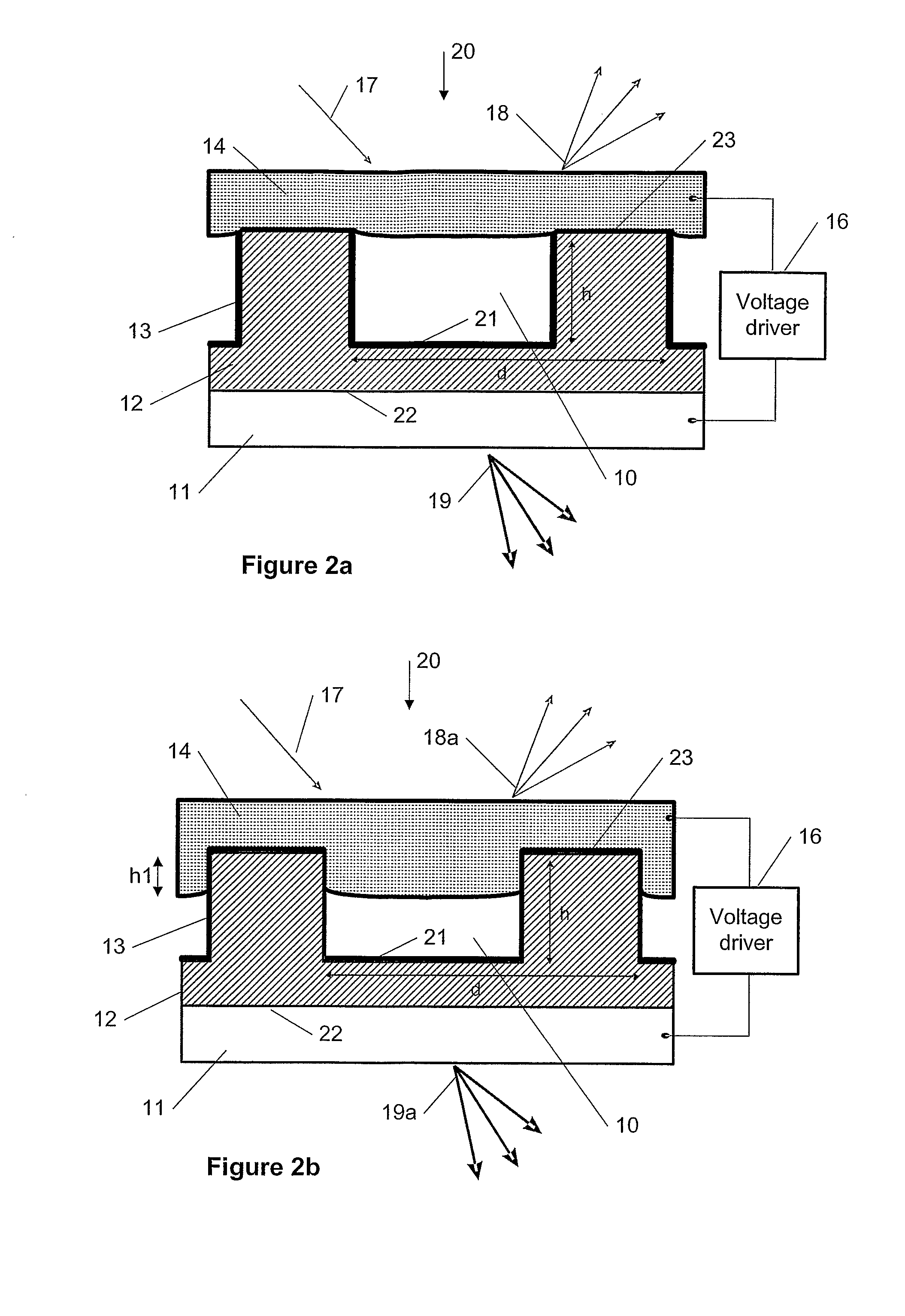
[0046]A new method, apparatus and software product are presented for modulation of optical intensity using electro-wetting (EW) diffraction gratings in the electronic devices with an electrical control signal. The EW diffraction gratings can be components of an element (e.g., a display) of the electronic device. Embodiments of the present invention provide a technical solution for utilizing electro-wetting (EW) to implement variable efficiency diffraction gratings.

[0047]For example, one solution is a direct view color display with continuously tunable pixel intensities, e.g., using the EW diffraction grating as a colored pixel, which provides fast response time and refresh rate, as described below. Other applications may be projection displays, front illuminating displays, field sequential displays, auto-stereoscopic displays, etc. Also, applications in areas other than displays are possible as well which can include (but not be limited to) areas utilizing optical beam splitting and...


PUM


Abstract

The specification and drawings present a new method, apparatus and software product for modulation of the optical intensity using electro-wetting (EW) diffraction gratings in the electronic devices with an electrical control signal. The EW diffraction gratings can be components of an element (e.g., a display) of the electronic device. Applications may include but are not limited to color displays, projection displays, front illuminating displays, field sequential displays, auto-stereoscopic displays, etc. Also, applications in areas other than displays are possible.

Description

TECHNICAL FIELD[0001]The present invention relates generally to electronic devices and, more specifically, to a modulation of optical intensity and / or redirection of optical path with an electrical control signal using electro-wetting (EW) diffraction gratings in the electronic devices.BACKGROUND ART[0002]There are many techniques which can be utilized for light intensity, direction modulation, phase modulation, optical switching, optical logic, etc., which may include (but are not limited to): electro-optical methods, liquid crystals, acousto-optics, non-linear optics methods, magneto-optics, etc. There are many technologies suitable for use in display panel applications, e.g., the most typical being LCDs (liquid crystal displays). The U.S. Pat. No. 5,659,330 “Electrocapillary Color Display Sheet” by N. K. Sheridon describes another method for displays which uses electro-wetting to control the shape of dyed liquid droplets that are placed inside a capillary sheet. The display requi...

Claims


Application Information

Patent Timeline
IPC IPC(8): G02B5/18
CPCG02B26/005G02B5/1828G02B5/18G02B26/08
Inventor RYYTTY, PASI
Owner NOKIA TECHNOLOGLES OY
Why Eureka
Try Eureka