Solid electrolytic capacitor
a technology of electrolytic capacitors and solids, which is applied in the direction of fixed capacitor details, casings/cabinets/drawers, electrical apparatus casings/cabinets/drawers, etc., can solve the problems of resin cracking, and achieve the effect of small leakage curren
- Summary
- Abstract
- Description
- Claims
- Application Information
AI Technical Summary
Benefits of technology
Problems solved by technology
Method used
Image

Examples
exemplary embodiment 1
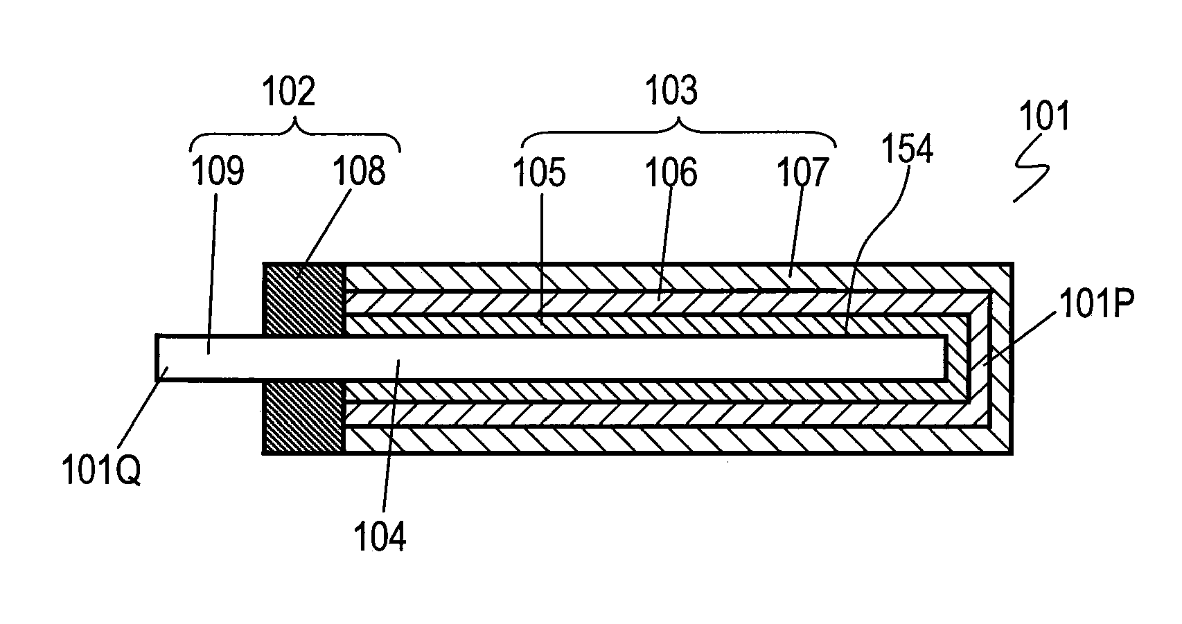
[0042]FIG. 1 is a side cross-sectional view of capacitor element 101 according to Exemplary Embodiment 1. Capacitor element 101 has a flat plate shape, and includes positive electrode body 104, positive electrode 102 provided on positive electrode body 104, and negative electrode 103 provided on positive electrode body 104. Positive electrode body 104 is a foil made of valve metal, such as aluminum, tantalum, titanium, or niobium, and has surface 154. Surface 154 is roughened by etching to enlarge its surface area. Alternatively, positive electrode body 104 can include a porous sintered body provided by sintering powder of valve metal, and a valve metal strip embedded in and bonded to the porous sintered body. Negative electrode 103 is provided at end 101P of capacitor element 101. Positive electrode 102 is provided at end 101Q opposite to end 101P.
[0043]Negative electrode 103 includes dielectric oxide layer 105 formed on surface 154 of positive electrode body 104, solid electrolyte...
examples 1 to 4
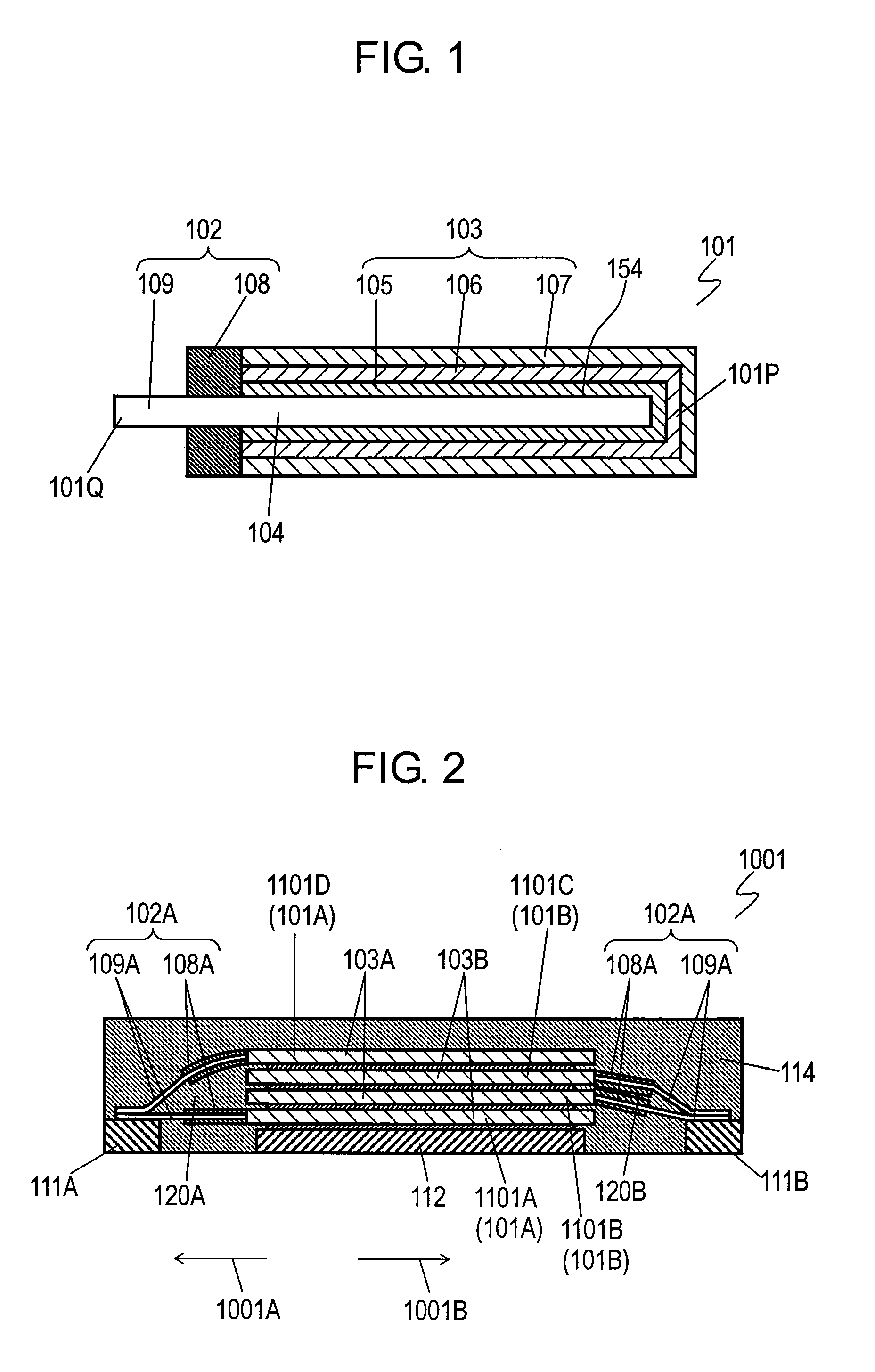
[0069]Solid electrolytic capacitors each including six capacitor elements 101 according to Embodiment 1 were manufactured as Examples 1 to 4. Negative electrodes 103 of capacitor elements 101 were stacked and bonded with conductive adhesive 113, and mounted on positive terminals 111A and 111B and negative terminal 112. The positive connection portions overlapped and were welded to positive terminals 111A and 111B. The negative electrodes of the capacitor elements were bonded to negative terminal 112 with conductive adhesive 113.
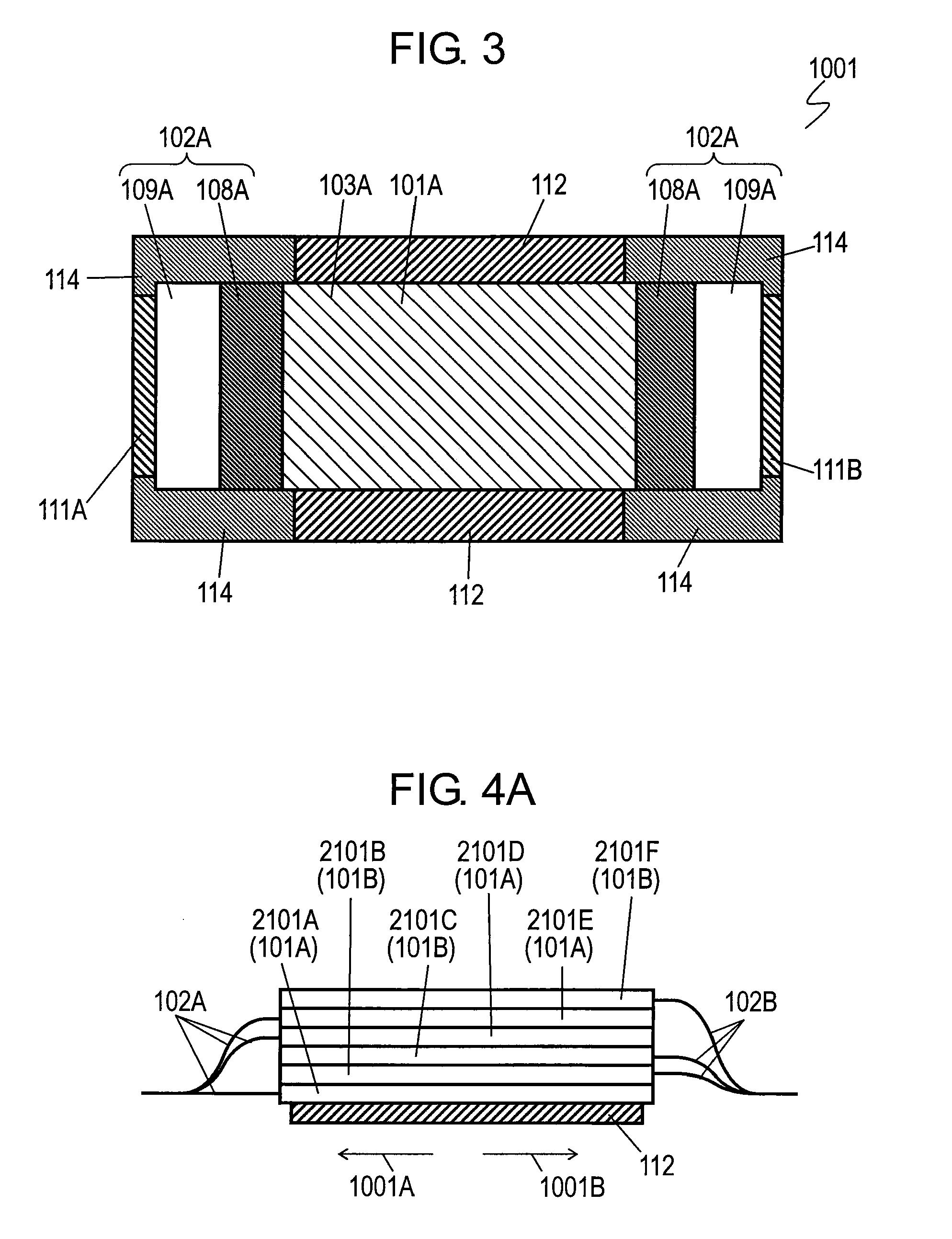
[0070]Then, stacked capacitor elements 101, positive terminals 111A, and 111B and negative terminal 112 were accommodated in a mold. Pellets of epoxy resin containing 80-90% by weight of silica having an average particle diameter of 60-80 μm were prepared. The pellets were melted at a temperature of 160-180° C. to be injected into the mold, and hardened to form package resin 114 by transfer molding. Thus, Examples 1 to 4 of the solid electrolytic capacitors w...
exemplary embodiment 2
[0088]FIG. 5 is a side cross-sectional view of solid electrolytic capacitor 2001 according to Exemplary Embodiment 2 of the present invention. FIG. 6 is a side cross-sectional view of capacitor elements 201 of solid electrolytic capacitor 2001. FIG. 7 is a cross-sectional view of solid electrolytic capacitor 2001 at lines 7-7 shown in FIG. 5.
[0089]The solid electrolytic capacitor includes plural capacitor elements 201 stacked, positive terminals 211, negative terminal 215, coupler 225 provided between capacitor elements 201 and negative terminal 215, and package resin 221 that covers capacitor elements 201. Each capacitor element 201 includes negative electrode 203 and positive electrode 202 extending from negative electrode 203. Each positive terminal 211 includes positive mounting portions 212 having positive electrodes 202 mounted thereon. Negative terminal 215 includes negative mounting portion 216 having negative electrode 203 mounted thereon. Coupler 225 has a cross section ha...
PUM
 Abstract
Description
Claims
Application Information