
High speed network interface with automatic power management with auto-negotiation

a network interface and automatic power management technology, applied in the field of computer networks and interface devices, can solve the problem of greater than specified power consumption of the interface, and achieve the effect of avoiding physical damage to the adapter and the system environmen

Inactive Publication Date: 2009-12-03
HEWLETT-PACKARD ENTERPRISE DEV LP +1
View PDF15 Cites 15 Cited by
  • Summary
  • Abstract
  • Description
  • Claims
  • Application Information

AI Technical Summary

Benefits of technology

The present invention provides a solution for managing the power of high-speed network interface devices, such as Gigabit Ethernet adapters, without the need for host software intervention. The invention uses logic and hardware resources on the network interface to force the medium interface unit to the lower speed protocol in response to an event signaling entry of the lower power mode. The network interface operates as a wake-up device in the lower power mode, using the lower speed protocol, and can detect a pattern in incoming packets and issue a reset signal to the host processor. The invention also includes a host processor that monitors the network interface for a wake-up event involving a loss of link or a change of link status on the network interface. Overall, the invention allows network interface devices to meet lower power specifications of modern standard bus systems and avoid physical damage to the adapter and the system environment.

Problems solved by technology

However, the interface consumes greater than the specified power when executing the high speed protocol.

Method used


Image

  • High speed network interface with automatic power management with auto-negotiation
  • High speed network interface with automatic power management with auto-negotiation
  • High speed network interface with automatic power management with auto-negotiation

Examples


Embodiment Construction

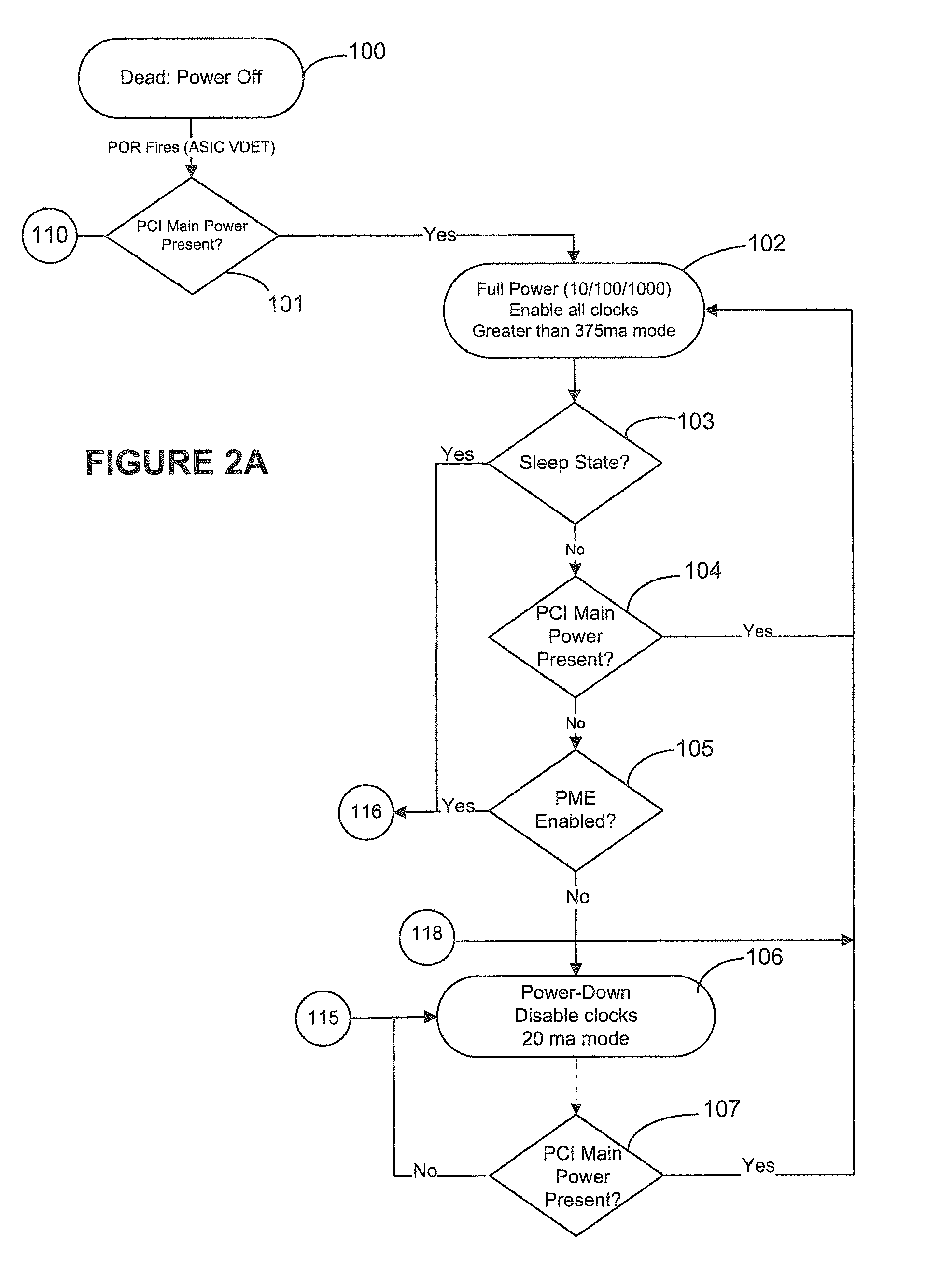
[0021]A detailed description of embodiments of the present invention is presented with reference to FIGS. 1, 2A and 2B.

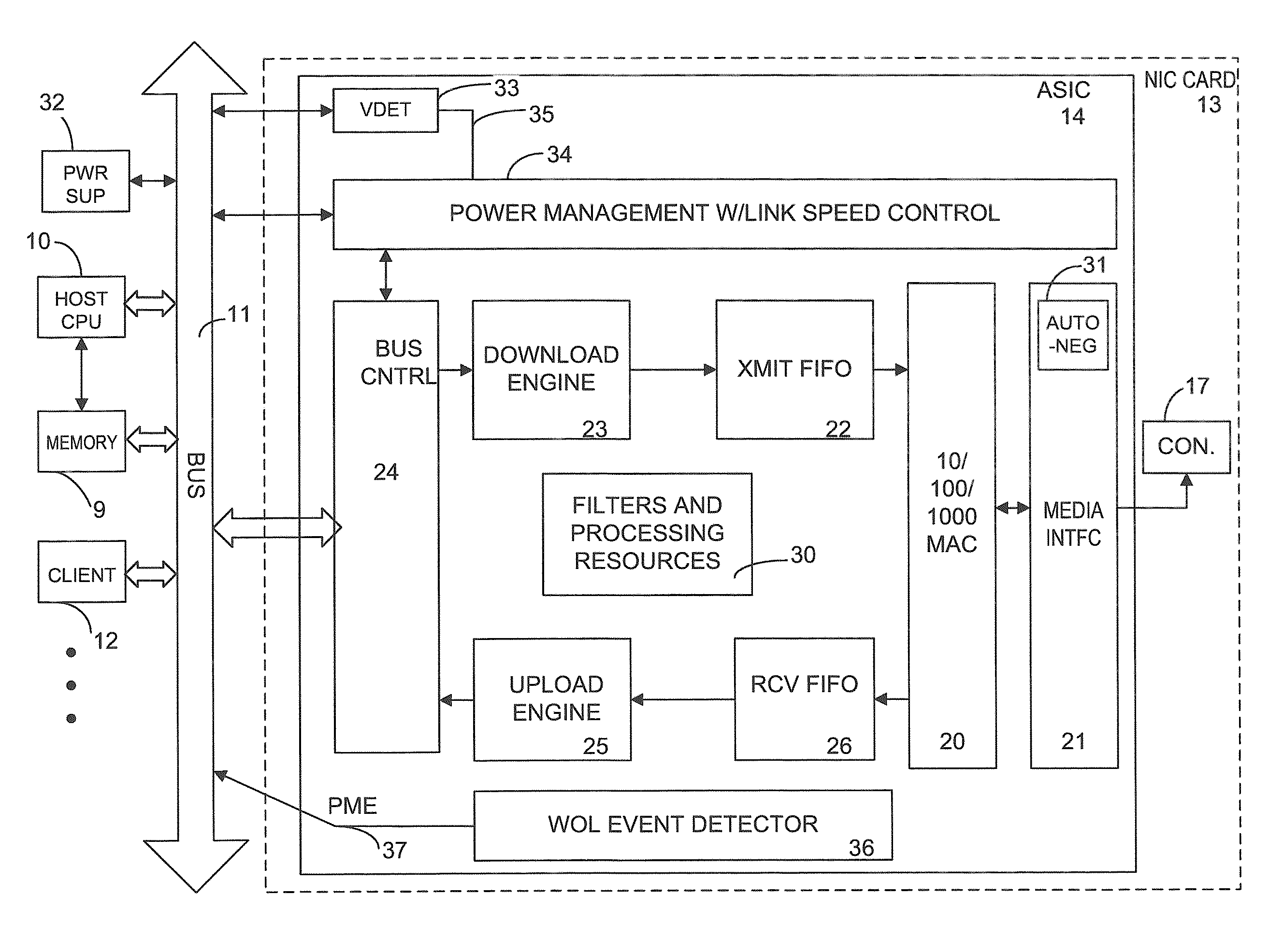
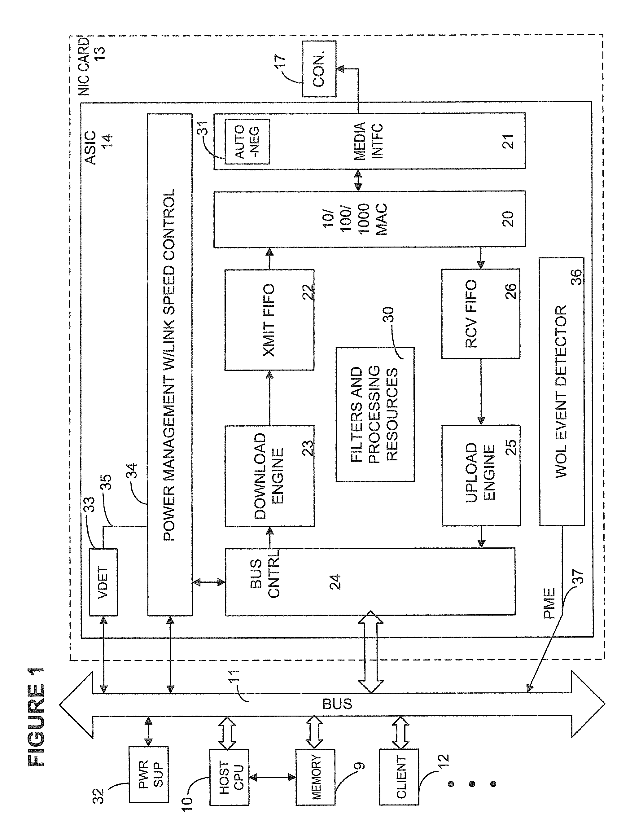
[0022]FIG. 1 provides a basic structural diagram of an embodiment of a computer system having a host CPU 10 coupled to a bus system 11, such as a bus compliant with a standard such as PCI or InfiniBand. CPU memory 9 is coupled to the CPU 10 and to the bus 11. The bus 11 interconnects a plurality of bus clients, including client 12 and the NIC 13 shown with expanded functional blocks. The NIC 13 includes an application specific integrated circuit (ASIC) 14. The ASIC 14 includes network interface functions for a Gigabit ETHERNET interface in this particular embodiment. Other embodiments provide interfaces to other types of the network media and protocols, including InfiniBand for example. In addition to the ASIC 14, other components are interconnected by and supported by the circuit board of the NIC 13. For example, a BIOS ROM (not shown), and a connector 17 to the ne...


PUM


Abstract

A computer system comprises host processor and a network interface, wherein the host processor includes resources supporting a full power mode, a lower power mode and a power down mode, as seen in standard system bus specifications such as PCI and InfiniBand. The network interface includes a medium interface unit coupled to network media supporting a least high speed protocol, such as a Gigabit Ethernet or high-speed InfiniBand, and a lower speed protocol, such as one of 10 Mb and 100 Mb Ethernet or a lower speed InfiniBand. Power management circuitry forces the medium interface unit to the lower speed protocol in response to an event signaling entry of the lower power mode. In the lower power mode, the network interface consumes less than the specified power when executing the lower speed protocol, and consumes greater than the specified power when executing the high speed protocol. Logic in the network interface operates in the lower power mode, and uses the lower speed protocol to detect a pattern in incoming packets. In response to the detection of said pattern, the logic issues a reset signal to the host processor. Thus, the network interface operates as a wake-up device in the lower power mode, using the lower speed protocol.

Description

BACKGROUND OF THE INVENTION[0001]1. Field of the Invention[0002]The present invention relates to computer networks and to interface devices for connecting host computers to networks. More particularly, the present invention relates to power management in high speed network interface devices supporting multiple link speeds.[0003]2. Description of Related Art[0004]Computer systems often include network interfaces that support high speed data transfers between a host computer and a data network. Such computer systems include an adapter such as a Network Interface Card, (NIC), or a chip for the network interface on the motherboard. Such adapters typically connect to a host processor via a bus.[0005]Many computer systems include power management logic which puts the system to sleep, or in a lower power mode, in response to activity in the system. When the system is asleep, for example, the operating system (OS) ceases operation. To bring the system awake, the operating system must be rel...

Claims


Application Information

Patent Timeline
Patent Type & Authority Applications(United States)
IPC IPC(8): G06F1/32
CPCG06F1/3203G06F1/3209Y02B60/44Y02B60/32G06F1/325Y02D30/00Y02D30/50
Inventor HENDERSON, NATHANWANG, CHI-LIEHU, BAODONG
Owner HEWLETT-PACKARD ENTERPRISE DEV LP
Learn More