Reagent dosing system and method of dosing reagent

a technology of dosing system and reagent, which is applied in the direction of machine/engine, electric control of exhaust treatment, separation process, etc., can solve the problems of difficult to achieve the match, the lean-burn engine cannot take advantage of the well-developed and effective 3, and the internal combustion engine can produce harmful chemical species in the exhaust stream

Inactive Publication Date: 2009-12-10
DELPHI TECH IP LTD
View PDF36 Cites 89 Cited by
  • Summary
  • Abstract
  • Description
  • Claims
  • Application Information

AI Technical Summary

Benefits of technology

[0080]controlling the positive-displacement metering pump in accordance with a control parameter which is dependent on the exhaust gas stream...

Problems solved by technology

It is well known that internal combustion engines can produce harmful chemical species in their exhaust streams.
Lean-burn engines are unable to take advantage of the well developed and effective 3-way catalyst systems that are universally used by homogeneous spark ignition engines.
However, under transient operating conditions, achieving this match is much more challenging due to catalyst temperature variation and NH3 storage effects such that conversion ratios of 85 to 90% are more typically achieved.
In order to achieve the necessary stability of pressure control in such a system requires sophistication, and therefore expense.
Moreover, metering accu...

Method used


Image

  • Reagent dosing system and method of dosing reagent
  • Reagent dosing system and method of dosing reagent
  • Reagent dosing system and method of dosing reagent

Examples


Embodiment Construction

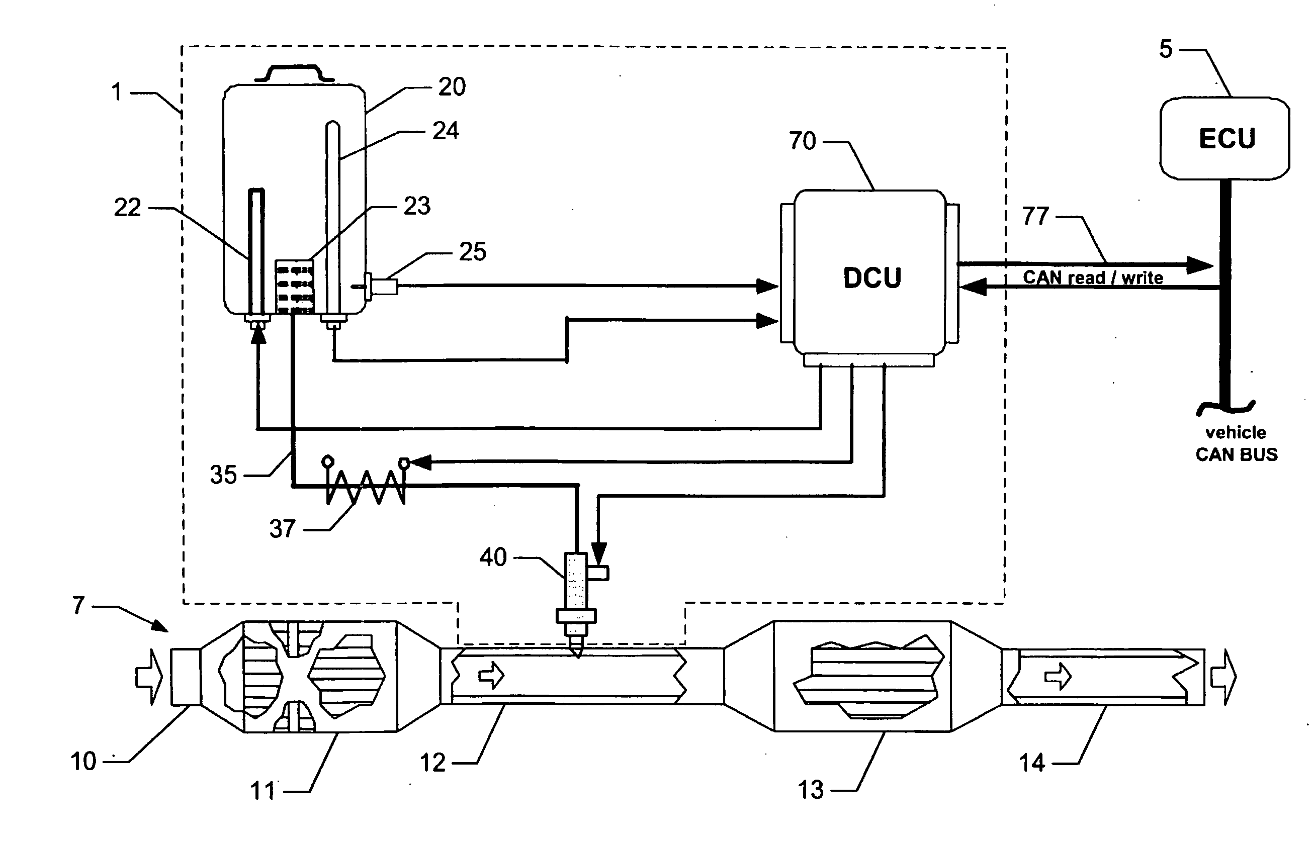
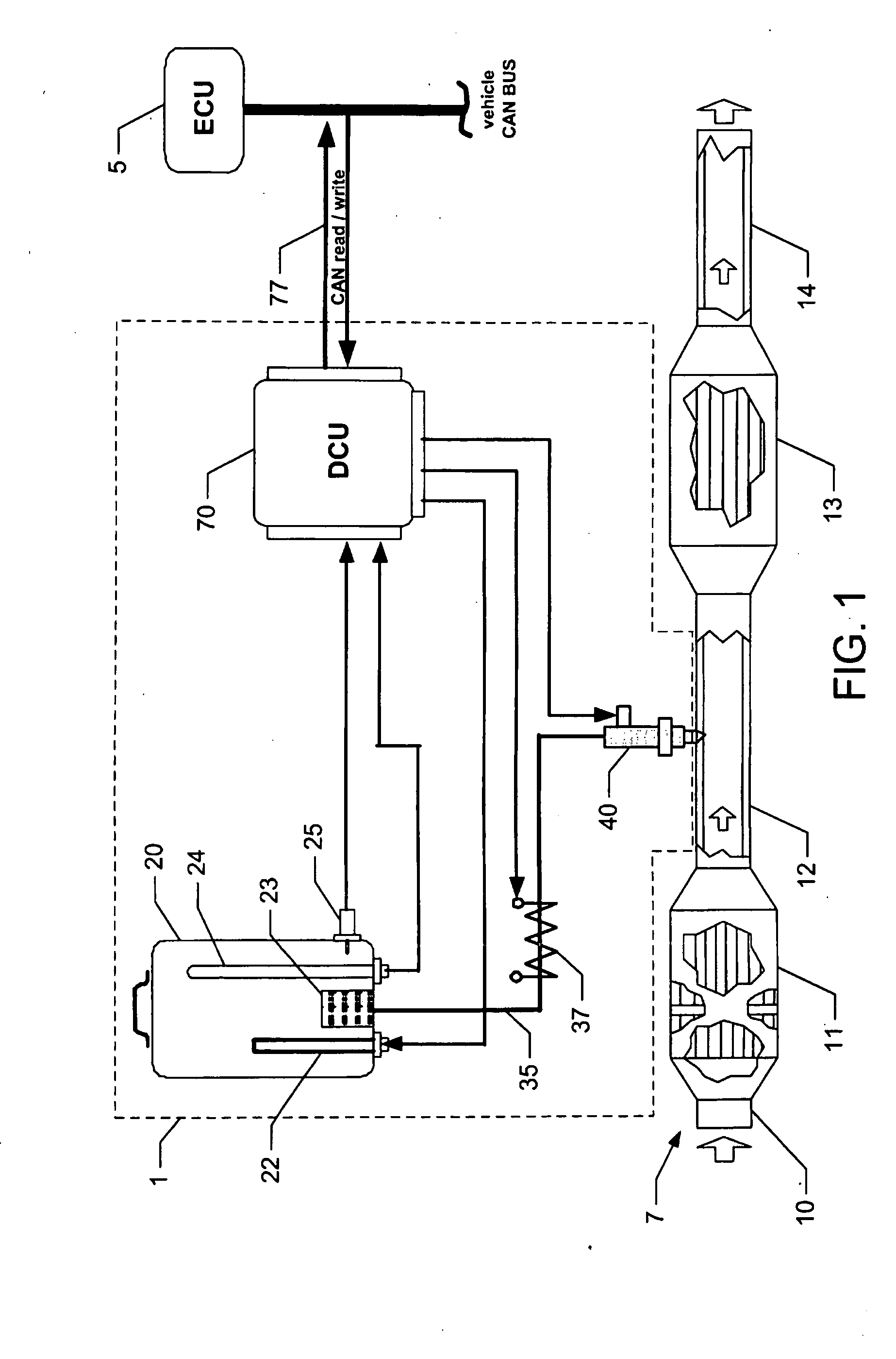
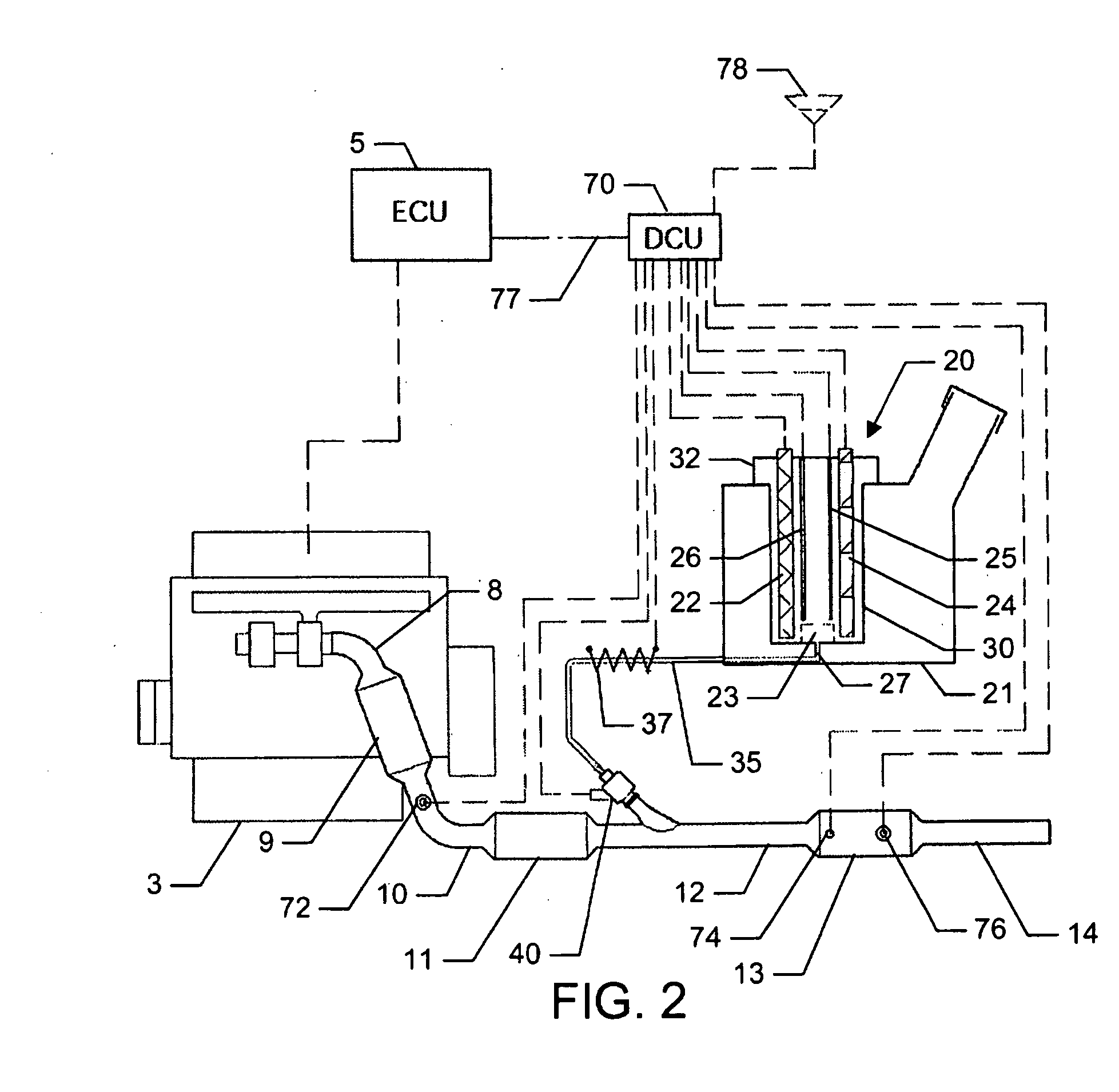
[0102]Referring to FIGS. 1 and 2, the SCR dosing system 1 is operable to inject a quantity of reagent (or reductant) into the exhaust gas stream emitted from an internal combustion engine 3. The internal combustion engine 3 is a diesel fuelled compression-ignition combustion engine.

[0103]The internal combustion engine 3 is controlled by an engine control unit (ECU)5. An exhaust system 7 is coupled to the internal combustion engine 3 for conveying exhaust gas emissions therefrom.

[0104]The exhaust system 7 comprises first, second, third and fourth portions 8, 10, 12, 14. The exhaust system 7 also includes a diesel oxidation catalyst 9, disposed between the first and second exhaust portions 8, 10, a diesel particulate filter 11 (DPF), disposed between the second and third exhaust portions 10, 12, and a selective catalytic reduction (SCR) catalyst 13, disposed between the third and fourth exhaust portions 12, 14.

[0105]During operation of the internal combustion engine 3, exhaust gas emi...


PUM


Abstract

A method of dosing a reagent into an exhaust gas stream of an internal combustion engine having an SCR catalyst, the method comprising injecting reagent from a reagent tank into the exhaust gas stream at a position upstream of the SCR catalyst using a reagent injector in accordance with a first dosing schedule in order to remediate a predetermined proportion of NOx in the exhaust gas stream, the first dosing schedule being associated with a first range of engine operating conditions; and injecting reagent from the reagent tank into the exhaust gas stream at a position upstream of the SCR catalyst using a reagent injector in accordance with a second dosing schedule in order to enable heat transfer between the reagent injector and said injected reagent, the second dosing schedule being associated with a second range of engine operating conditions.
Dosing in accordance with said first or said second dosing schedule is carried out in dependence on whether engine operating conditions lie within said first or said second range of engine operating conditions, and the proportion of NOx in the exhaust gas stream which is remediated by dosing using said second dosing schedule is less than said predetermined portion. A reagent dosing system is also provided for dosing a reagent into the exhaust gas stream of an internal combustion engine, comprising a reagent tank for storing a supply of reagent, an injector module comprising an atomising dispenser and a positive-displacement metering pump which draws reagent from the reagent tank and delivers it to the dispenser a supply line coupling the reagent tank to the injector module, and a dosing control unit operable to control the injector module to inject reagent into the exhaust gas stream. A priming pump is provided to urge reagent along the supply line toward the injector module under selected conditions.

Description

TECHNICAL FIELD[0001]The present invention relates to a reagent dosing system for dosing a reagent into the exhaust gas stream of an internal combustion engine and to a method of dosing a reagent into the exhaust gas stream of an internal combustion engine.BACKGROUND TO THE INVENTION[0002]It is well known that internal combustion engines can produce harmful chemical species in their exhaust streams. It is therefore desirable to eliminate or at least reduce such pollutants to levels low enough that human health is not adversely affected. As a result of the high temperatures that are reached during a combustion event, many chemical species are produced from the oxidation of hydrocarbon fuels, including the oxides of nitrogen (NO and NO2, collectively referred to as NOx). Due to their impact on human health, many countries in the global community have enacted legislation that seeks to limit the emission of NOx from both mobile and stationary sources, and many techniques have been devel...

Claims


Application Information

Patent Timeline
IPC IPC(8): F01N9/00F01N3/00F01N13/08
CPCF01N3/021F01N3/0814F01N3/0807F01N3/0878F01N3/106F01N3/208F01N11/00F01N2240/25F01N2240/36F01N2250/02F01N2250/12F01N2250/14F01N2260/024F01N2410/04F01N2410/12F01N2560/021F01N2560/026F01N2570/14F01N2610/02F01N2610/03F01N2610/1413F01N2610/1433F01N2610/146F01N2900/0412F01N2900/08F01N2900/1814Y02T10/47Y02T10/24F01N13/009F01N13/011F01N3/035Y02A50/20Y02T10/12Y02T10/40B01D53/90B01D53/94F01N3/206F01N3/2882F01N3/36F01N9/00
Inventor DINGLE, PHILIP J.G.HARDY, MARTIN PAULZUELCH, ROMAN STEFAN
Owner DELPHI TECH IP LTD
Why Eureka
Try Eureka