Electrolytic Erosion Preventing Insulated Rolling Bearing, Manufacturing Method Thereof, and Bearing Device

a technology of insulating rolling bearings and electrolytic erosion prevention, which is applied in the direction of mechanical equipment, rotary machine parts, coatings, etc., can solve the problems of shortening the life of rolling bearings, cracks, chips, and difficulty in ensuring high levels of insulation performance, durability, low cost, and high electrical resistivity. , the effect of high electrical resistivity

Active Publication Date: 2009-12-10
NSK LTD
View PDF21 Cites 29 Cited by
  • Summary
  • Abstract
  • Description
  • Claims
  • Application Information

AI Technical Summary

Benefits of technology

[0130]According to the electrolytic erosion preventing insulated rolling bearing, and the manufacturing method thereof, of the present invention, it is possible to ensure high levels of insulation performance, durability, and low cost, at the same time.
[0131]That is, a ceramic sprayed layer that contains alumina at 99 percent by weight or more is used, but such a ceramic sprayed layer has a comparatively high electrical resistivity (excellent insulating characteristics). Accordingly, if it is ensured that the thickness of the insulating coating after grinding is 0.25 mm or more, provided that the application is for rotation support portion of a rotating shaft of an electric motor for general use or for rail car, or for a rotation support portion of a rotating shaft for an electrical generator, or furthermore for a rotation support portion of a general purpose motor for general industry or the like, a sufficient electrolytic erosion prevention effect can be ensured.
[0132]Moreover, in the case where the insulating coating 6 is formed by grinding the surfaces of a ceramic sprayed layer formed on the surfaces other than the raceway surface, the thickness of the ceramic sprayed layer is 0.4 mm or less except on the continuous folded over portions between adjacent surfaces, and the thickness of the insulating coating obtained by grinding the ceramic sprayed layer is 0.25 mm or more, it is possible to ensure high levels of insulation performance, durability, and low cost, at the same time.
[0133]That is, in the case of the construction described in the third aspect, a ceramic sprayed layer which contains alumina at greater than or equal to 97 percent by weight and zirconia at greater than or equal to 0.5 to 2.5 percent by weight, is used. However, such a ceramic sprayed layer has a comparatively high electrical resistivity (excellent insulating characteristics). Therefore, if it is ensured that the thickness of the insulating coating after grinding is greater than or equal to 0.25 mm, provided that the application is for a rotating shaft of an electric motor for general use or for railroad rocking stock, or for a rotation support portion of a rotating shaft for an electrical generator, a sufficient electrolytic erosion prevention effect can be ensured.
[0134]Furthermore, in the first, third, sixth and eleventh aspects of the invention, in order to ensure that the thickness of the insulating coating after grinding is greater than or equal to 0.25 mm, even if the thickness of the ceramic sprayed layer before grinding is less than or equal to 0.4 mm, a sufficient grinding allowance can be ensured. If the thickness of the ceramic sprayed layer can be limited to less than or equal to 0.4 mm, the thickness of the ceramic sprayed layer coating the two continuous folded over portions between adjacent surfaces can be limited to less than 0.5 mm (furthermore less than or equal to 0.48 mm). If the thickness of the ceramic sprayed layer is approximately 0.5 mm (furthermore 0.48 mm), the thickness dimension is not excessive, so it is difficult for damage such as cracks, chips or the like to occur even if it is left as it is (even if the thickness dimension is not reduced by grinding). Accordingly, the time and effort for grinding parts of the ceramic sprayed layer which coat the continuous folded over portions, are eliminated and hence the cost can be reduced. Moreover, cost reduction can also be achieved by keeping the thickness of the ceramic sprayed layer thinner {formerly greater than or equal to 0.5 mm (typically about 0.6 to 0.7 mm) to less than or equal to 0.4 mm}.
[0135]Furthermore, according to the electrolytic erosion preventing insulated rolling bearing of the second, third, seventh and eighth aspects of the invention, by incorporating either one of titanium oxide and zirconia in an alumina sprayed layer, it is possible to ensure high levels of insulation performance, durability, low cost, and excellent external appearance at the same time.

Problems solved by technology

In the case where electrical current flows into a rolling bearing, so-called electrolytic erosion occurs whereby erosion progresses in the parts that serve as pathways of current, shortening the life of the rolling bearing significantly.
However, in the case of the known conventional electrolytic erosion preventing insulated rolling bearing, which is disclosed in the above-mentioned Patent Documents 1 to 3, it is difficult to ensure high levels of insulation performance, durability, and low cost, at the same time.
The ceramic sprayed layers are brittle, so if the thickness dimension becomes too large, it is likely to cause damage such as cracks, chips and the like.
Since the continuous folded over portions 9 themselves do not make contact with other parts such as the housing and the like, even if the ceramic sprayed layer is damaged, it is unlikely to cause a problem from the aspect of maintaining the insulation performance.
However, in the case where a broken fragment of ceramic falls and enters the inside of the rolling bearing, it is likely to generate damage such as making an indentation in the surface or the like of the inner ring raceway 2, the outer ring raceway 4, or the rolling contact surface of each of the rolling elements 5, which is undesirable.
Grinding the surface parts of the continuous folded over portions 9 causes an increase in the cost, for no gain.
However, in the cases of the inventions disclosed in Patent Documents 4 and 5, manufacture is difficult, so neither of them can achieve low cost.
However, as is disclosed in Patent Document 6, in the case of white alumina, the yield of the material (alumina grain) at the time of sprayed layer formation is poor, increasing the cost.
However, according to an experiment performed by the inventor of the present invention, it is found that gray alumina having the composition disclosed in Patent Document 6 does not always maintain sufficient insulation performance.
On the other hand, in the case where white alumina is used, it is found that, if the grain diameter of alumina sprayed is controlled appropriately, although the amount of cost increase is limited, irregular coloring occurs on the surface, resulting in a poor external appearance of the product.
That is, the alumina sprayed layer has minute voids inside it in its normal condition, and in the case where moisture enters the voids, the insulation performance deteriorates.
Such irregular coloring is not a problem in terms of insulation performance, but since it degrades the external appearance of the product, it is not desirable.
If the discharge phenomena occur, current flows into the rolling bearing, and there is a possibility that the aforementioned electrolytic erosion will occur.
In the case where electrolytic erosion occurs in such places, the seal deteriorates, leading to a shortened life of the rolling bearing.
Therefore, they are not desirable as materials for coating the fitting surface of a bearing device, which must be accurate.
Moreover, the above-described PBT is sometimes not sufficiently thermal resistant or strength, so it is inevitably not desirable as a material for coating the interface surface.
However, in the case of the construction disclosed in Patent Document 12 having such a configuration, the manufacturing cost increases proportionate to forming the metal layer 19.
In the case of the construction disclosed in Patent Document 13, it is also inevitable that the cost will be increased.
However, if the thickness of the film increases, the cost of the material increases.
Especially, in the case where the insulating coating is made of a ceramic sprayed layer, the duration of the spraying operation increases, which also incurs an increase in the cost.
However, in the case where the construction disclosed in Patent Document 6 is used in a large sized rolling bearing, there is a possibility that sufficient insulation performance cannot always be obtained.
However, if the film thickness is increased by greater than or equal to a certain value, good insulation performance proportionate to the increase in the cost cannot always be expected.
Accordingly, in the case of considering the material cost and the spraying operation duration, depending on the quality of the insulating coating material, it is sometimes difficult to obtain an insulating coating with sufficient insulation performance.
However, in the case where the brittle ceramic insulating coating is formed on the inner peripheral surface of the inner ring, which is an interference fit, there is a possibility that cracks or chips occur in the insulating coating.
However, since creeping occurs between the inner ring and the shaft, this is not realistic.
However, in the case where the ratio of the titanium oxide is increased this much, there is a possibility that sufficient impedance cannot be ensured.
However, in order to increase the thickness, it is necessary to perform operations of coating the insulating coating 6 a plurality of times (multi-layer coating), causing an increase in the cost of manufacturing the electrolytic erosion preventing insulated rolling bearing, which is undesirable.
However, from the aspects of strength or cost, in most of cases, it is difficult to make the housing 15b or the outer ring spacer from insulating material.
Moreover, even if they can be discriminated, an edge (vertex) occurring due to marking is likely to be a start point of discharge, and in the case where discharge occurs, damage due to electrolytic erosion is produced in the rolling bearing.

Method used


Image

  • Electrolytic Erosion Preventing Insulated Rolling Bearing, Manufacturing Method Thereof, and Bearing Device
  • Electrolytic Erosion Preventing Insulated Rolling Bearing, Manufacturing Method Thereof, and Bearing Device
  • Electrolytic Erosion Preventing Insulated Rolling Bearing, Manufacturing Method Thereof, and Bearing Device

Examples


twelfth example

of the Embodiment

[0279]FIGS. 16 and 17 show a twelfth example of the embodiment of the present invention. In the case of the present example, partial cone concave chamfers 23, which are inclined at 45 degrees with respect to the central axis of the outer ring 3h, are formed between the two axial end faces 8 of the outer ring 3h and the inner peripheral surface 33. The two chamfers 23 are indented parts. Continuous portions 22b between the outer peripheral rims of the two chamfers 23 and the two axial end faces 8 are convex surfaces 34 whose cross-sections have a curve radius r for a partial circle shape of 1 mm or more. Moreover, it is ensured that the distance L between the inner peripheral edge parts of the two chamfers 23 and the axial end faces 8 (or between the surface of an outer diameter side insulating coating 39 coating the inner peripheral edge parts of the two chamfers 23 and the surface of the outer diameter side insulating coating 39 coating the two axial end faces 8) i...

thirteenth example

of the Embodiment

[0284]FIG. 18 shows a thirteenth example of the embodiment of the present invention. In the case of the present example, the indented part formed as a part drawn towards the inner diameter of the axial end face 8 of the outer ring 3h, being a coated bearing ring, is a plurality (three in the example in the figure) of joined partial cone concave surfaces 35a, 35b and 35c, whose angles of inclination with respect to the central axis of the outer ring 3h, being a coated bearing ring, are different, and the generatrix shapes of which are straight lines. The apex angles of the continuous portions 22c, 22d and 22e between the adjacent partial cone concave surfaces 35a, 35b and 35c, and between the partial cone concave surface 35c, which is located closest to the outer diameter side, and the axial end face 8, are all 150 degrees or more (preferably 165 degrees or more). Furthermore, in the case of the present example, it is ensured that the distance L between the surface o...

working example 1

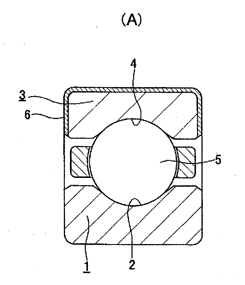
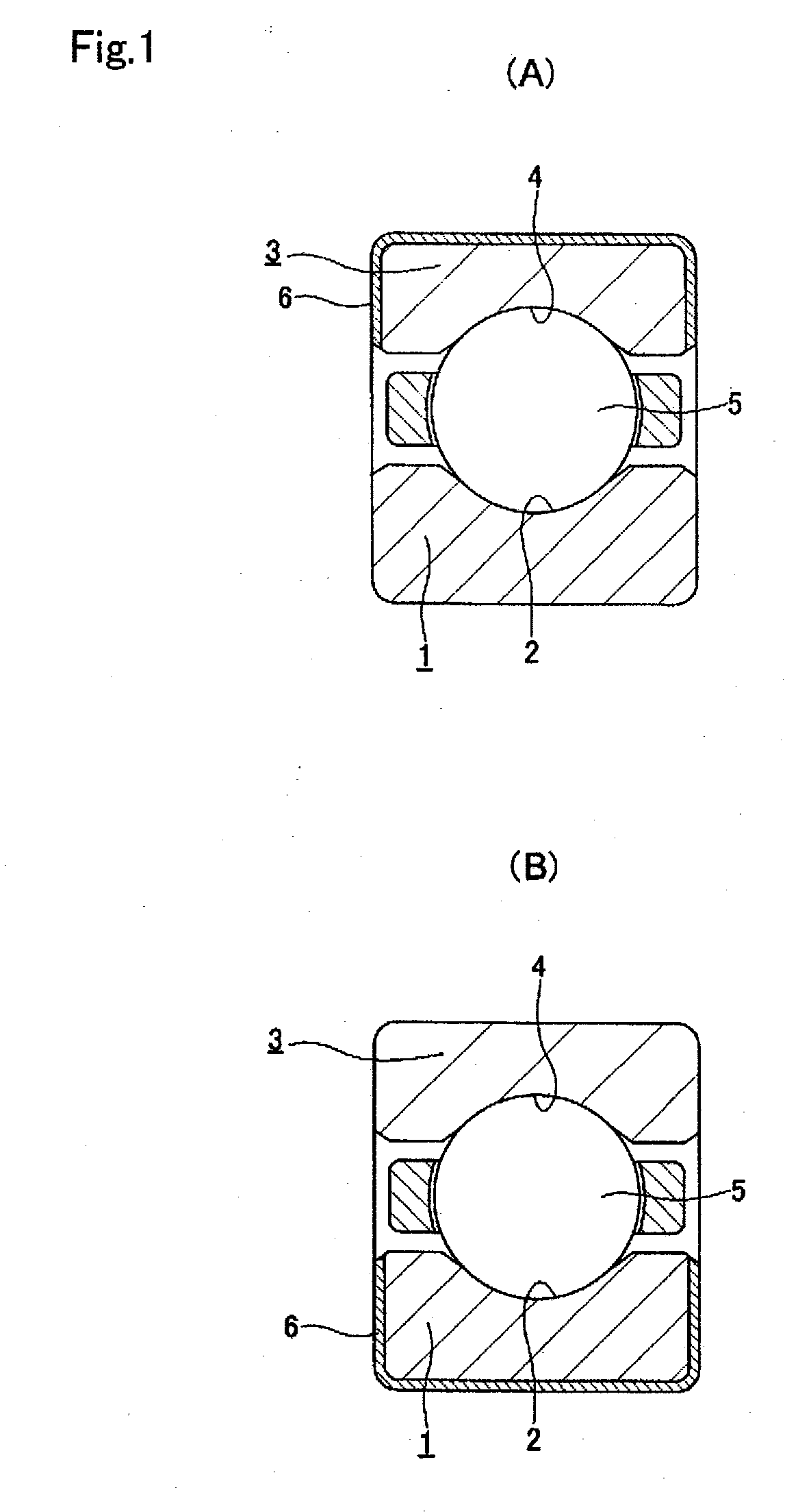
[0292]There follows a description of experiments performed in order to confirm the effects of the present invention. The following is described with reference to FIGS. 1 to 3. First is a description of an experiment performed in order to determine the influence of the thickness of the ceramic sprayed layer and the content by percentage of alumina in the ceramic sprayed layer on non-uniformity in the thickness of the ceramic sprayed layer and the insulating characteristics. An outer ring 3 (inner diameter of the outer ring: 142 mm) constituting a single row deep groove ball bearing (outer diameter: 170 mm, inner diameter: 80 mm, width: 39 mm), whose bearing designation was 6316, was used in this experiment.

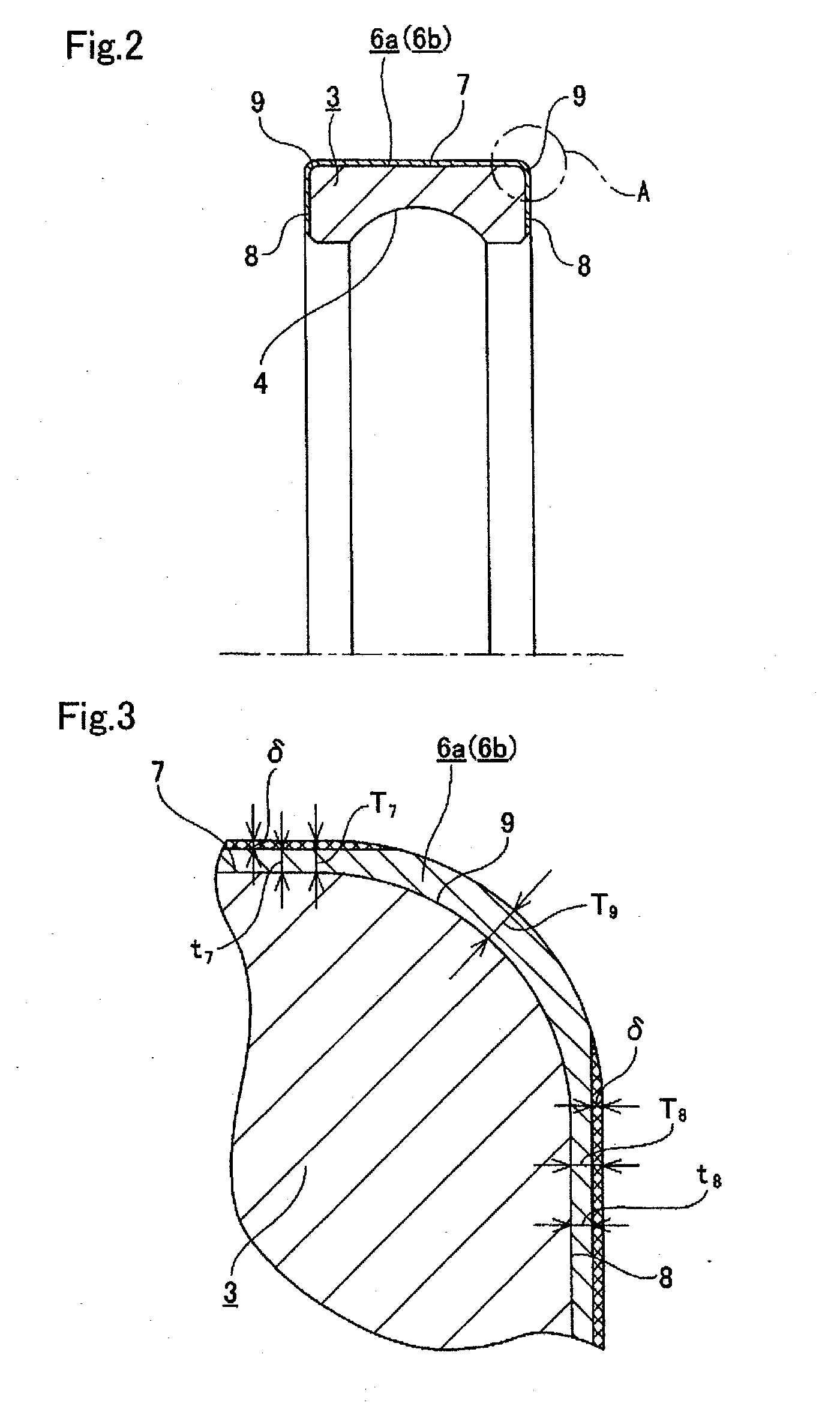
[0293]First is a description of an experiment performed in order to determine the influence of the thickness dimensions T7 and T8 of the ceramic sprayed layers formed on the outer peripheral surface 7 and the two axial end faces 8 of the outer ring 3 (non-uniformity in the thicknes...


PUM

PropertyMeasurementUnit
thicknessaaaaaaaaaa
thicknessaaaaaaaaaa
particle sizeaaaaaaaaaa

Abstract

In order to ensure high levels of insulation performance, and low cost, and have an excellent external appearance, as a ceramic constituting an insulating coating 6 being a ceramic coating layer, one with alumina as its main component, and in which the content of titanium oxide is limited to 0.01 to 0.2 percent by weight is used. Moreover, a particle size of ceramic forming the coating layer is 10 to 50 μm, and average particle size is 15 to 25 μm. By limiting the content of titanium oxide, the insulating coating 6 can be made thin, and by limiting the particle size the film thickness accuracy can be improved, thus simplifying finishing. Moreover, by mixing of titanium oxide, deterioration of the external appearance after sealing can be prevented. As a result, the above problem is solved.

Description

TECHNICAL FIELD[0001]This invention relates to an electrolytic erosion preventing insulated rolling bearing and a manufacturing method thereof. This electrolytic erosion preventing insulated rolling bearing is incorporated in a rotation support portion into which there is a possibility of current flowing, such as a rotation shaft of a general-purpose electric motor for general industry, an electrical generator (electrical generator of a wind mill or the like), a main motor for a rail car, or a medical device (CT scanner or the like). Specifically, this invention relates to a large sized electrolytic erosion preventing insulated rolling bearing whose outer diameter is 200 mm or more.[0002]Moreover, this invention is a bearing assembly which constitutes a rotation support portion of a general-purpose electric motor for general industry, an electrical generator (electrical generator of a wind mill or the like), a main motor for a rail car, or a medical device (CT scanner or the like). ...

Claims


Application Information

Patent Timeline
Patent Type & Authority Applications(United States)
IPC IPC(8): F16C33/62B21K1/04
CPCF16C19/52F16C33/62F16C33/64Y10T29/49689F16C33/7843F16C41/008F16C2202/30F16C33/7826F16C2223/42F16C33/586F16C19/06
Inventor KONNO, KATSUHIROKOTAKI, KENJIMURAI, TAKASHIFUJII, OSAMUWATANABE, TETSUOMATSUSHITA, TAKAYUKI
Owner NSK LTD
Why Eureka
Try Eureka