

Substrate and the application
a technology of substrate and application, which is applied in the field of substrate, can solve the problems of high energy consumption, high cost of materials, and large budge in the cost of energy to maintain heating in the winter or cooling in the summer of buildings and homes, and achieve the effects of reducing global warming, increasing energy efficiency, and saving energy
- Summary
- Abstract
- Description
- Claims
- Application Information
AI Technical Summary
Benefits of technology
Problems solved by technology
Method used
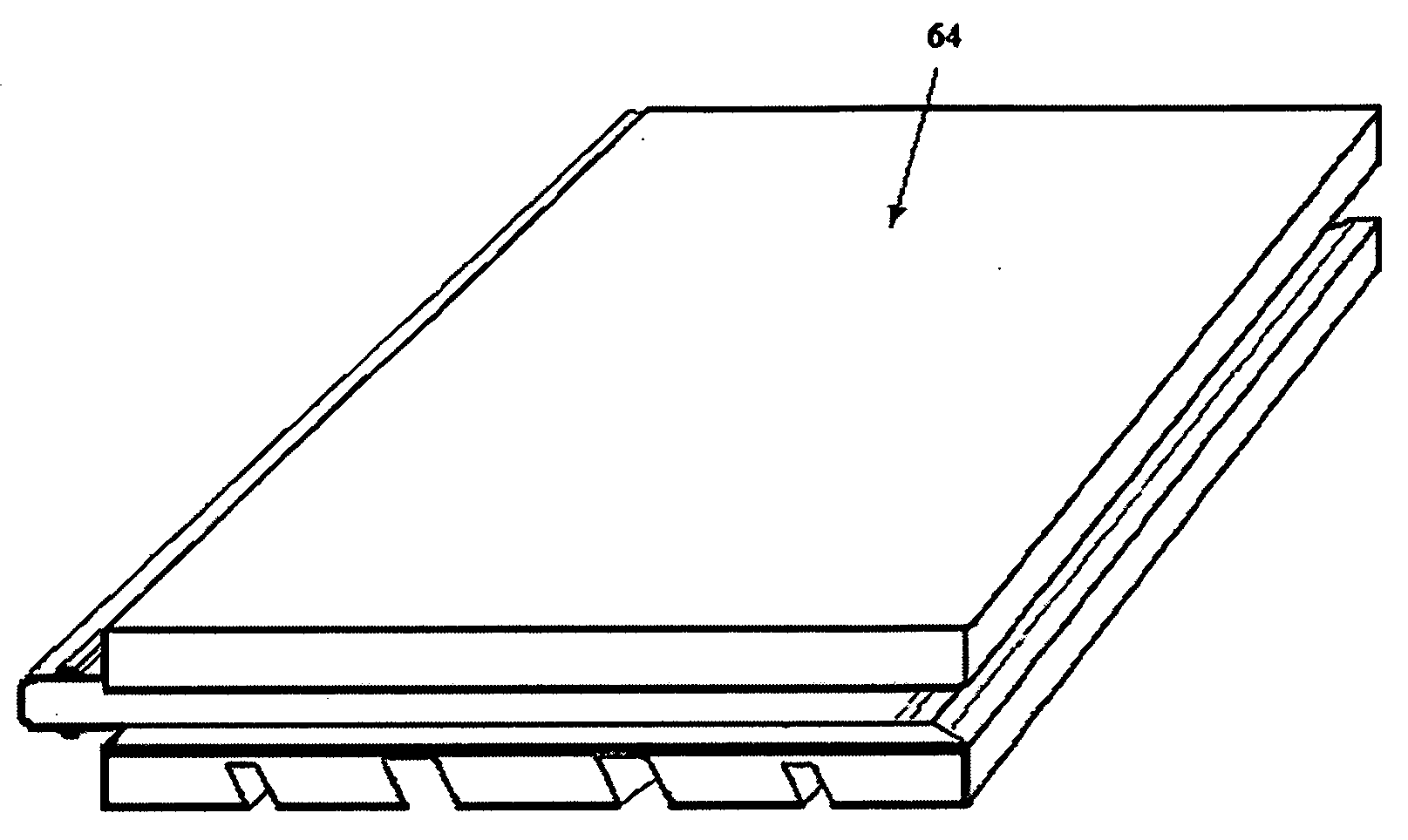
Image

Examples
example 1
Process and Preparation of a Substrate with Different Cellular Structured Foams as the Thermal Insulation Materials and an EDP Panel with the Look and Appearance of Concrete Wall Pattern
[0133]Step 1: Substrate with Homogenous and Heterogeneous Foam Structures as the Thermal Insulation Materials and the Preparation
[0134]A substrate with a thermal insulation material comprising different foams and skins is processed from PVC (polyvinyl chloride) compounds A and B as shown in Table 1, respectively. Compositions A and B except ingredient HFC134 in composition B are identical. All the ingredients except HFC134 are weighted and added in the order into a bowl mixer (Henshel) with a temperature control less than 150 F. After mixing, the mixture is then dropped through a hopper onto a single screw extruder at a temperature of 130 C and palletized with a strand die. A twin screw extruder (2.5 inch, 32 / 1 L / D, Akron Extruders, Canal Fulton, Ohio) was used to product a foam material. Physical bl...
example 2
Process and Preparation of a Substrate with a Skeleton Structured Thermal Insulation Material and an EDP Panel with Thermal Reflecting and Electromagnetic Wave Shielding Materials and Appearance of Bricks
[0140]Step 1: A substrate with a Foam Filled Skeleton Structured Material and the Preparation
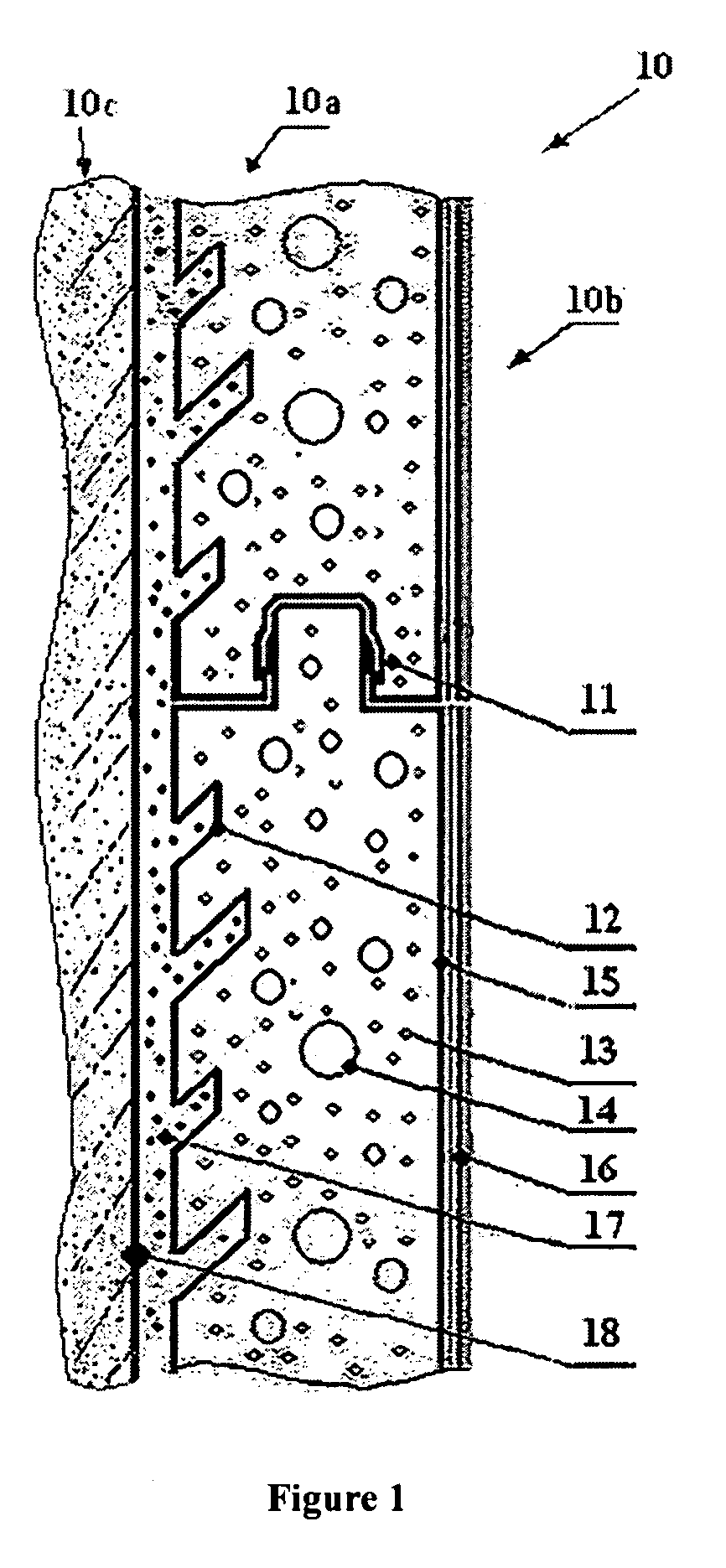
[0141]A substrate with a thermal insulation material comprising a skeleton is formed from PVC (polyvinyl chloride) composition C as shown in Tables 3 and 4.
[0142]All the ingredients in Table 3 are weighted and added in the order into a bowl mixer (Henshel) with a temperature control less than 150 F. After mixing, the mixture is then dropped through a hopper onto a single screw extruder at a temperature of 130 C and palletized with a strand die. A twin screw extruder (2.5 inch, 32 / 1 L / D, Akron Extruders, Canal Fulton, Ohio) with a modified screw design is used to process the composition. The die designed for a substrate (22.75 cm×3.00 cm) as shown in FIG. 11 is a crosshead die to receiving in...
example 3
Process and Preparation of an EDP Panel with Appearance of Glass
[0150]A substrate prepared from Step 2 of Example 1, B is sanded (P120). After sanding, a layer of a quick set adhesive tinted to dark blue (Dow Corning Q3-6093 Weatherable Silicone Adhesive) is applied (5 mils) onto the face and sides of the substrate, and a tempered glass plate (22.75 cm×22.75 cm×0.32 cm) is laid over the adhesive on the face of the substrate. While the adhesive is wet, the glass plate is evenly applied with a pressure (2 psi, pounds per square inches) on the top to allow any air bubble to flow out and the adhesive to cure. After the adhesive is set, a frameless EDP panel with the look and appearance of glass is prepared (the R value listed in Table 2, ASTM C518).
PUM
| Property | Measurement | Unit |
|---|---|---|
| Angle | aaaaa | aaaaa |
| Temperature | aaaaa | aaaaa |
| Temperature | aaaaa | aaaaa |
Abstract
Description
Claims
Application Information