Erosion prevention method and member with erosion preventive section

a technology of erosion prevention and turbine blades, applied in the direction of turbines, soldering devices, manufacturing tools, etc., can solve the problems of rear-stage turbine blades being eroded, the erosive environment is harsher, and the erosion of turbine blades is also problemati

a technology of erosion prevention and turbine blades, applied in the direction of turbines, soldering devices, manufacturing tools, etc., can solve the problems of rear-stage turbine blades being eroded, the erosive environment is harsher, and the erosion of turbine blades is also problemati

US20090308847A1Inactive Publication Date: 2009-12-17KK TOSHIBA

Image

  • Erosion prevention method and member with erosion preventive section
  • Erosion prevention method and member with erosion preventive section
  • Erosion prevention method and member with erosion preventive section

Examples


first embodiment

Configuration

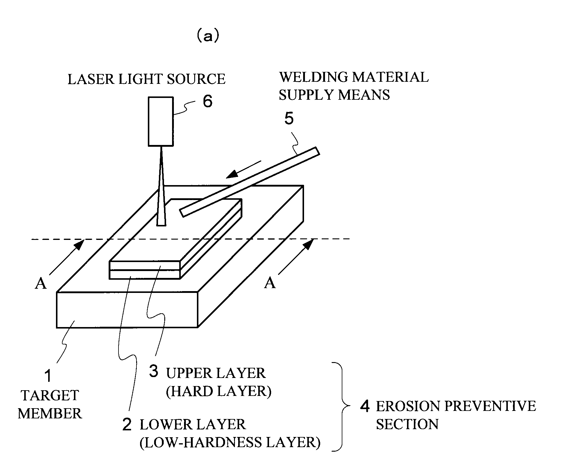
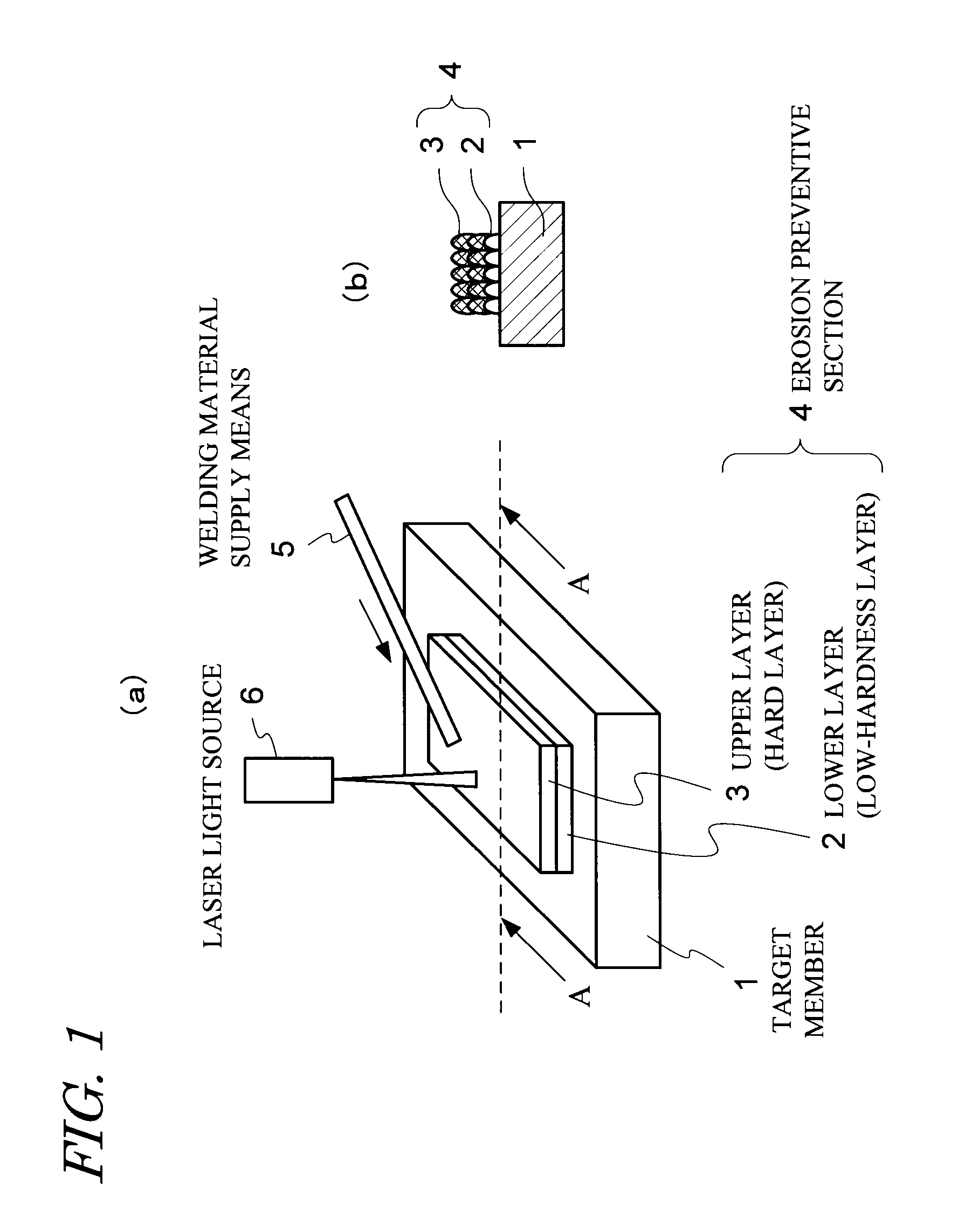
[0040]FIG. 1(a) is an image diagram illustrating an erosion prevention method according to a first embodiment of the present invention. FIG. 1(b) is a schematic cross-sectional diagram of FIG. 1(a) viewed in the direction of arrow A.

[0041]As illustrated in FIG. 1, an erosion preventive section 4, comprising a lower layer (low-hardness layer) 2 of an austenitic material, and an upper layer (hard layer) 3 of a hard material, such as stellite, harder than the low-hardness layer 2, is formed by laser build-up welding on an erosion prevention target portion of a target member 1, such as a turbine rotor blade, that is used in an erosive environment, i.e. a portion susceptible to erosion caused by liquid droplets and solid particles in a use environment. Specifically, laser build-up welding is carried out through irradiation of a laser beam from a laser light source 6 while a welding material supply means 5 supplies an austenitic material and a hard material in the form of, fo...

second embodiment

Configuration

[0060]FIG. 6 illustrates an example of an erosion prevention method according to a second embodiment of the present invention. FIG. 6(a) is a perspective-view diagram illustrating a turbine rotor blade 41; FIG. 6(b) is an enlarged diagram illustrating the tip of the turbine rotor blade 41 illustrated in FIG. 6(a); and FIG. 6(c) is a perspective-view diagram illustrating a state in which an erosion preventive section 43 replaces a target portion 42 (portion enclosed by a broken line) at the tip of the turbine rotor blade 41.

[0061]As illustrated in FIG. 6, the erosion prevention method of the present embodiment is an erosion prevention method in which the target member is a turbine rotor blade 41 being used in an erosive environment. The leading edge portion of the turbine rotor blade 41 is the target portion 42 that requires erosion countermeasures. The erosion preventive section 43 is provided through laser-fusion of a hard material powder that is then build-up welded, ...


PUM

PropertyMeasurementUnit
thicknessaaaaaaaaaa
thicknessaaaaaaaaaa
thicknessaaaaaaaaaa

Abstract

A method is provided, which ensures reliability during manufacture and in the use environment, and allows affording erosion prevention capability in an inexpensive manner, to an erosion-susceptible portion such as turbine rotor blades. An erosion preventive section 4, comprising a lower layer (low-hardness layer) 2 of an austenitic material, and an upper layer (hard layer) 3 of a hard material, such as stellite, harder than the low-hardness layer 2, is formed by laser build-up welding on a portion, which is susceptible to erosion caused by liquid droplets and solid particles in a use environment, of a target member 1 such as a turbine rotor blade. Laser build-up welding is carried out through irradiation of a laser beam from a laser light source 6 while a welding material supply means 5 supplies an austenitic material and a hard material in the form of, for instance, a rod, powder or the like.

Description

TECHNICAL FIELD[0001]The present invention relates to a method for preventing erosion at portions of various kinds of member having portions that are susceptible to erosion caused by liquid droplets and solid particles in a use environment, and more particularly, relates to an erosion prevention method for turbine blades and the like that are used in turbine equipment.BACKGROUND ART[0002]Members such as turbine blades are ordinarily used in turbine equipment. FIG. 9 is a cross-sectional diagram illustrating the structure of a steam turbine. In FIG. 9, the reference numeral 901 denotes a main steam pipe, 902 denotes a reheat steam pipe, 903 denotes a turbine rotor, 904 denotes a low-pressure outer casing, and 906 denotes a crossover pipe. A low-pressure inner casing 905 is housed in the low-pressure outer casing 904, and turbine rotor blades (turbine moving blades) 907 and turbine stator blades 908 are disposed in the interior of the low-pressure inner casing 905.[0003]Members such a...

Claims


Application Information

Patent Timeline
17 Dec 2009
Publication
US20090308847A1
IPC
B23K9/04
CPC
B23K15/0086; B23K2201/001; B23K26/3206; B23K35/0244; B23K26/345; B23K35/004; B23K35/007; B23K26/3213
Inventors
KAMIMURA, KENJI; SHIIHARA, KATSUNORI