
Fluid Actuator, and Heat Generating Device and Analysis Device Using the Same

a technology of heat generation device and actuator, which is applied in the direction of positive displacement liquid engine, piston pump, instruments, etc., can solve the problem of difficulty in unidirectional driving of fluid, and achieve the effect of reducing the resistance of the fluid channel, avoiding damage to the directivity of the surface acoustic waves, and increasing the driving for

Inactive Publication Date: 2009-12-24
KYOCERA CORP +1
View PDF9 Cites 8 Cited by
  • Summary
  • Abstract
  • Description
  • Claims
  • Application Information

AI Technical Summary

Benefits of technology

[0015]An object of the present invention is to provide a fluid actuator capable of driving with a high output at a relatively low voltage and allowing downsizing and weight reduction.
[0041]The heat generating device according to the present invention is a heat generating device utilizing the fluid actuator as a cooler and has a substrate mounted with this heat generating device, while the fluid channel is provided on the substrate mounted with the heat generating device. According to this structure, the fluid channel can be utilized as a radiation channel passing through the vicinity of the heat generating device and can cool the heat generating device by moving heat generated from the substrate mounted with the heat generating device to the fluid, and high cooling efficiency can be expected.

Problems solved by technology

However, the conventional fluid actuators have the following problems:
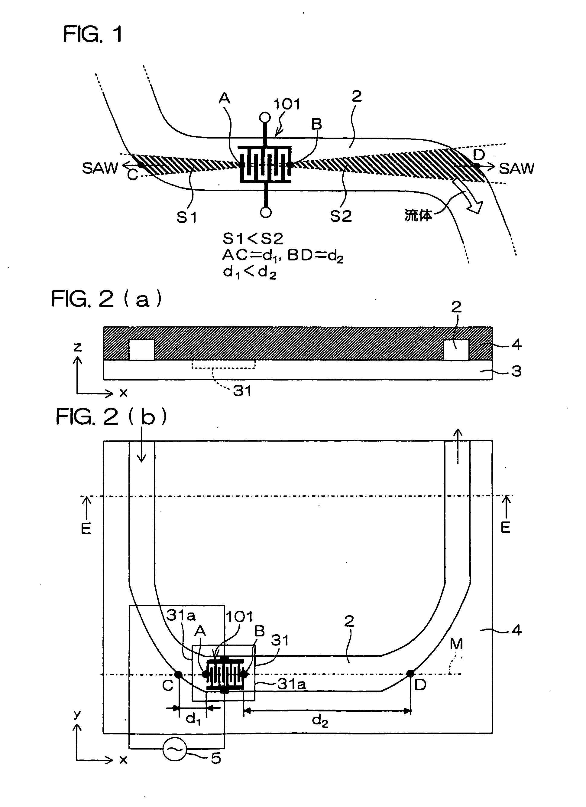
The micropump employing surface acoustic waves according to Patent Document 1 employs an electrode having a constant pitch constituted by meshing a pair of interdigital electrodes with each other, and hence it is difficult to unidirectionally drive a fluid even when generating surface acoustic waves from this electrode;

Method used


Image

  • Fluid Actuator, and Heat Generating Device and Analysis Device Using the Same
  • Fluid Actuator, and Heat Generating Device and Analysis Device Using the Same
  • Fluid Actuator, and Heat Generating Device and Analysis Device Using the Same

Examples


application examples

[0235]FIGS. 26(a) and 26(b) are a plan view and a sectional view taken along the line Q-Q showing an example of applying the fluid actuator according to the present invention to a device generating heat (hereinafter generically referred to as “heat generating device”) such as an integrated circuit, an external storage device, a light-emitting device or a cold-cathode tube.

[0236]Referring to FIGS. 26(a) and 26(b), a part of a semiconductor substrate is employed as a lid body 4 of the fluid actuator. An SOI (Silicon on Insulator) substrate having an SiO2 sandwiched between silicon layers as an insulating layer, for example, is employed as the semiconductor substrate.

[0237]A semiconductor circuit 32 is formed on a lower silicon layer 23 of the semiconductor substrate. An upper silicon layer 25 on an insulating layer 24 is etched by ICP-RIE through a mask of an aluminum film as described above, for forming a meandering fluid channel 2. The side of the semiconductor substrate provided wi...

examples

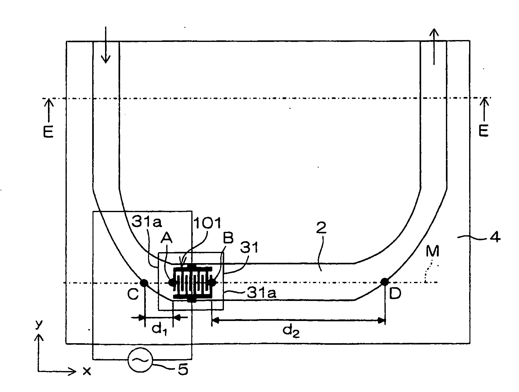
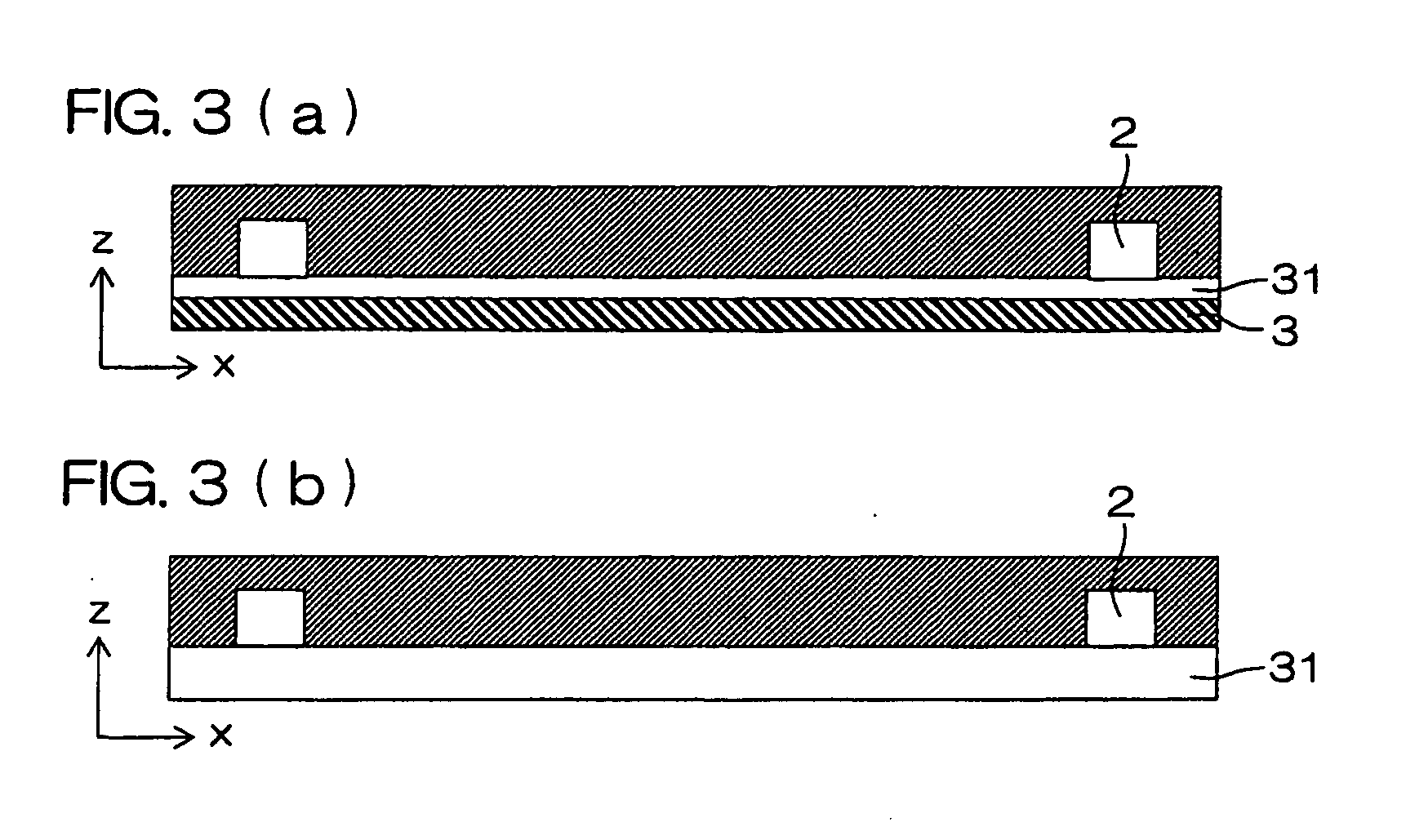
[0259]As to the fluid actuator according to the present invention, a manufacturing method therefor is described with reference to the structure shown in FIGS. 2(a) and 2(b) and 4(a) to 4(c), unless otherwise stated.

[0260]As the substrate 3, the substrate 3 entirely formed by the piezoelectric substrate 31 is employed (see FIG. 3(b)). While any substrate may be employed as the piezoelectric substrate 31 so far as the same is a piezoelectric ceramic substrate or a piezoelectric single-crystalline substrate having piezoelectricity, a single-crystalline substrate of lead zirconate titanate, lithium niobate or potassium niobate having high piezoelectricity is desirably employed so that the driving voltage can be reduced. For example, a single-crystalline 128° Y-rotation X-direction propagation substrate of lithium niobate (LiNbO3) can be employed.

[0261]Photoresist (hereinafter abbreviated as resist) is applied onto the piezoelectric substrate 31 by spin coating, for example. Then, photol...


PUM

PropertyMeasurementUnit
distanceaaaaaaaaaa
voltageaaaaaaaaaa
heightaaaaaaaaaa

Abstract

A fluid actuator includes a piezoelectric body (31), a fluid channel (2) having the piezoelectric body (31) on a part of the inner wall thereof and enabling a fluid to move inside, and a surface acoustic wave generation portion (101) for driving the fluid in the fluid channel by surface acoustic waves generated from a interdigital electrode formed on the surface of the piezoelectric body (31) facing the fluid channel (2). The surface acoustic wave generation portion (101) is arranged at the position offset from the center of the fluid channel (2). The fluid actuator can perform drive with a low voltage and drives the fluid in a narrow fluid channel in a single direction.

Description

TECHNICAL FIELD[0001]The present invention relates to a fluid actuator for causing a constant flow or a circulating flow in a fluid with surface acoustic waves (SAW). The present invention also relates to a heat generating device and an analysis device using the fluid actuator.BACKGROUND ART[0002]The speed of a microprocessor unit (MPU) has recently been remarkably increased. At present, the working frequency reaches not less than several GHz, and is in the process of further speed increase. Speed increase of the MPU is realized by increasing the integration density, and hence the heat generation density is inevitably increased. In the MPU having the maximum speed at present, the total heat generation amount reaches not less than 100 W and the heat generation density reaches not less than 400 W / mm2, and the heat generation amount is also continuously increased due to further speed increase.[0003]In some cases, a fan or a water cooler is provided on the upper surface of the MPU packa...

Claims


Application Information

Patent Timeline
Patent Type & Authority Applications(United States)
IPC IPC(8): H01L41/047H01L23/473G01N33/00F04B17/00H10N30/87
CPCF04B17/003F04F7/00F04D33/00F04B43/046
Inventor TSUYOSHI, HIROTAKATSUYOSHI, RYUSUKESUGUYAMA, SUSUMU
Owner KYOCERA CORP
Learn More