Method for the Electrolytic Production of Self-Supporting Conductive Nanocomposite Elements

a technology of conductive nanocomposite elements and electrolysis, which is applied in the field of energy storage using batteries, can solve the problems of high cost of entire process, unfavorable mechanical strength of copper nanoelements on copper substrates, and complicated industrial scale implementation

Inactive Publication Date: 2009-12-24
UNIV DE PICARDIE JULES VERNE +1
View PDF9 Cites 70 Cited by
  • Summary
  • Abstract
  • Description
  • Claims
  • Application Information

AI Technical Summary

Problems solved by technology

However, in that method, the copper layer forming a substrate obtained by electrochemical and / or chemical deposition in the case of the nanoelements is necessarily porous, and the length of the nanoelements in the final self-supporting element is dictated by the thickness of the membrane since the formation of the copper film on the surface of the membrane starts only when the surface of the pores of the membrane is completely covered with copper.
Furthermore, the fact that the copper nanoelements on the copper substrate are hollow is unfavorable to the mechanical strength of the self-supporting element, and also to its use as a current collector, the quantity of current conveyed through the hollow elements being less than with solid nanoelements.
This technique is complicated to implement on an industrial scale and makes the entire process expensive.
Furthermore, it does not allow a self-supporting element consisting of just one metal to be obtained when the intended metal cannot be applied in film form by PVD or CVD.

Method used


Image

  • Method for the Electrolytic Production of Self-Supporting Conductive Nanocomposite Elements
  • Method for the Electrolytic Production of Self-Supporting Conductive Nanocomposite Elements
  • Method for the Electrolytic Production of Self-Supporting Conductive Nanocomposite Elements

Examples


example 1

Deposition of Cu Nanowires on a Cu Substrate

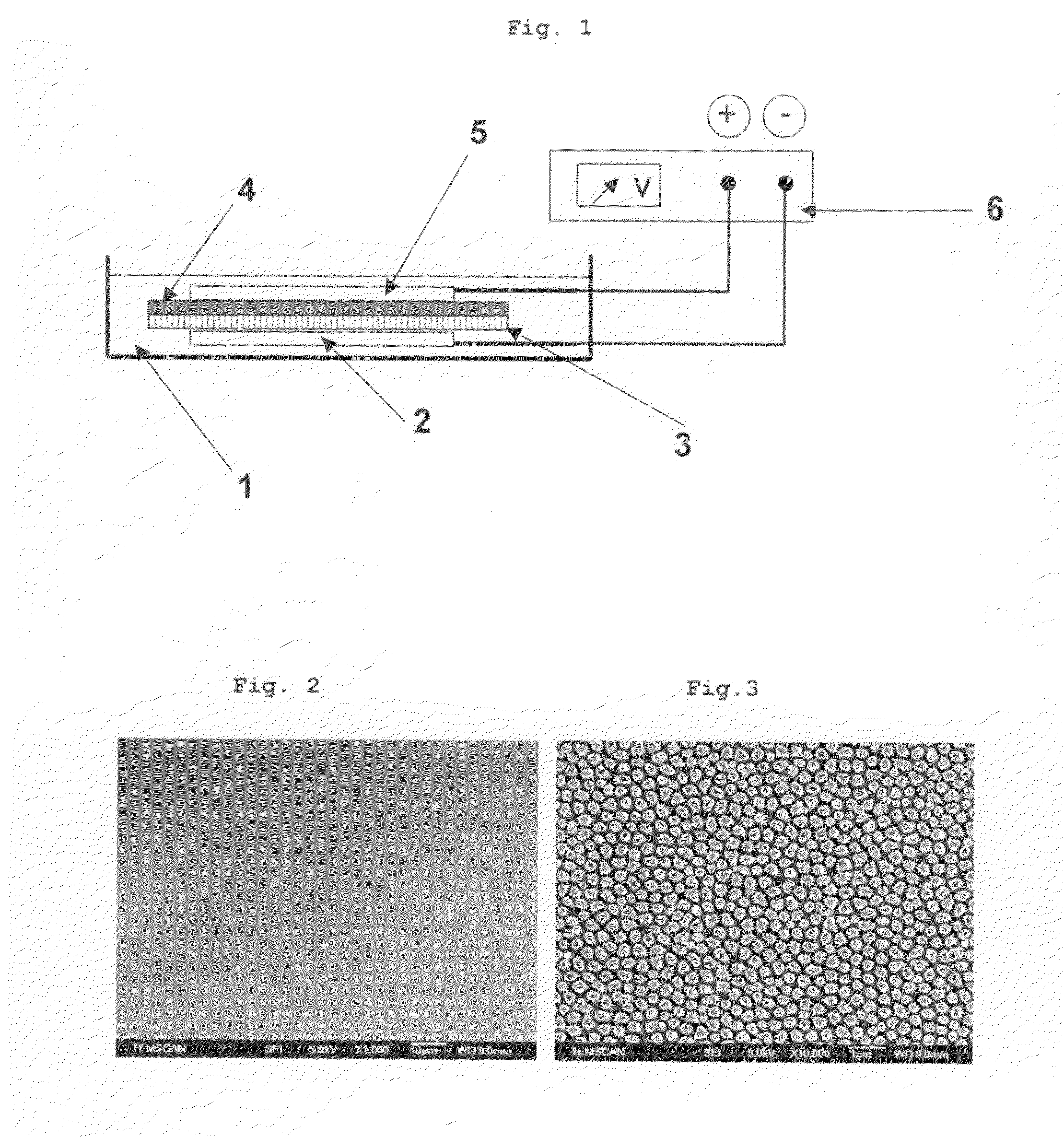
[0072]The method was employed in an electrochemical cell containing an electrolyte in which an assembly, consisting of the following elements kept in contact with one another by pressure and stacked in the order mentioned, was immersed:[0073]copper foil, forming the cathode;[0074]alumina membrane;[0075]cellulose foil, forming the separator;[0076]copper foil, forming the anode.

[0077]The cathode and the anode were connected to the negative terminal and to the positive terminal, respectively of a potentiostat.

[0078]The copper foils forming the cathode and the anode respectively had a thickness of 500 μm.

[0079]The alumina membrane was a membrane sold under the name Anodisc by Whatman. It had a thickness of 50 μm and the diameter of the substantially cylindrical pores was 200 nm.

[0080]The electrolyte was an aqueous solution of (100 g / l) CuSO4, 20 g / l (NH4)2SO4 and 80 g / l DETA (diethylenetetra-amine).

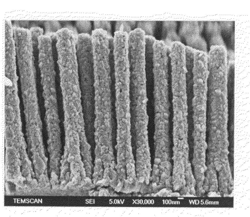
[0081]The electrolysis was carried out with c...

example 2

Deposition of Sn Nanowires on a Cu Substrate

[0086]The operating method of example 1 was repeated, using:[0087]a Cu foil having a thickness of 500 μm, forming the cathode;[0088]an Anodisc alumina membrane;[0089]an Sn foil having a thickness of 500 μm, forming the anode.

[0090]The electrolyte was an aqueous solution containing SnSO4 (97 g / l), HSO4 (30 g / L), tartaric acid (30 g / l), a PEG 3500 polyethylene glycol (0.35 g / l), gelatin (1 g / l) and Na2SO4 (30 g / l).

example 3

Deposition of Copper Nanowires on a 3300 V / 100 A IGBT Chip

[0091]The operating method of example 1 was repeated, using:[0092]a 3300 V / 100 A IGBT (insulated-gate bipolar transistor) chip, forming the cathode;[0093]an Anodisc alumina membrane; and[0094]a Cu foil having a thickness of 500 μm forming the anode.

[0095]The electrolyte was an aqueous solution containing SnSO4 (97 g / l), H2SO4 (30 g / l), tartaric acid (30 g / l), a PEG 3500 polyethylene glycol (0.35 g / l), gelatin (1 g / l) and Na2SO4 (30 g / l).

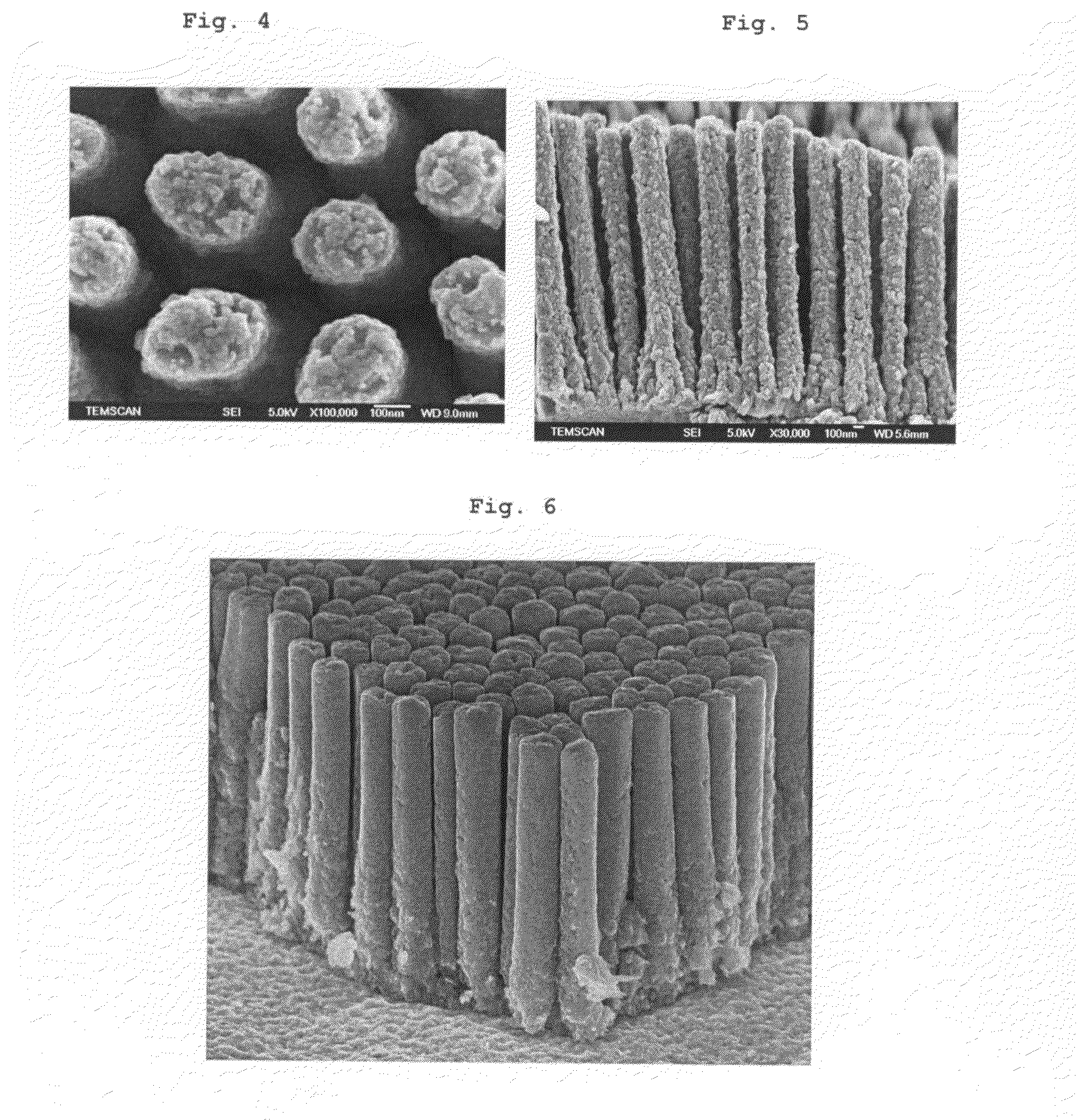
[0096]FIG. 6 shows an FEG-SEM micrograph of the product obtained.


PUM

PropertyMeasurementUnit
thicknessaaaaaaaaaa
thicknessaaaaaaaaaa
thicknessaaaaaaaaaa

Abstract

The invention relates to a self-supporting composite element and to a method of producing same. The composite element comprises a substrate of electronic conductive material which is covered with metal nanowires that are essentially oriented along a plane that is perpendicular to the substrate. The element is produced in a cell comprising a cathode which is formed by the substrate to be covered, one or more anodes and an electrolyte which is formed by a solution of a precursor of the metal material and optionally containing a conductive ionic salt, a flat porous membrane which is placed between the cathode and each of the anodes and a spacer element between each membrane and the anode adjacent thereto, the different constituent parts of the cell being maintained in contact.

Description

[0001]The invention relates to a method for depositing a nanostructured metal coating on an electronically conductive substrate and to the substrates thus coated.BACKGROUND OF THE INVENTION[0002]In the field of energy storage using batteries, the properties of the electrodes, and especially of the current collectors that the electrodes include, are an important element as regards the overall performance of the batteries. In order for a material to be able to be used as a collector, it is desirable for it to have a high electronic conductivity, good electrochemical stability and a large area of contact with the active material. Nanomaterials have a high area / volume ratio thereby increasing the reaction rates, by reducing the diffusional limitations, and the use of nanomaterials for production of current collectors is under development.[0003]It is known to prepare nanostructured electrically conductive materials in the form of solid or hollow fibers using a porous membrane either elec...

Claims


Application Information

Patent Timeline
Patent Type & Authority Applications(United States)
IPC IPC(8): H01G9/016C25D5/02H01M4/02H01M6/04H01M6/14H01M6/18H01M4/134H01M4/58H01M10/052H01M10/36
CPCC25D3/02C25D1/006C25D7/00H01M4/134H01M4/5825H01M4/661H01M4/70H01M4/75H01M10/052Y02E60/122H01G11/30Y02E60/13H01L2924/0002C25D5/022C25D11/045Y10T428/1241Y10T428/12438C25D1/04H01L2924/00Y02E60/10Y02P70/50
Inventor SIMON, PATRICETABERNA, PIERRE-LOUISCAMBRONNE, JEAN-PASCALLEBEY, THIERRY
Owner UNIV DE PICARDIE JULES VERNE
Why Eureka
Try Eureka