Vibration damping novel surface structures and methods of making the same

a surface structure and vibration damping technology, applied in the field of turbines, can solve the problems of energy dissipation, many of the components of the turbine may be subjected to vibrational stress during the operation of the turbine, and the fatigue life of the components

Active Publication Date: 2009-12-24
GENERAL ELECTRIC CO
View PDF7 Cites 27 Cited by
  • Summary
  • Abstract
  • Description
  • Claims
  • Application Information

AI Technical Summary

Benefits of technology

[0010]In a certain aspect, at least one embodiment generally relates to a method of making the gas turbine or turbine component partially or fully coated with a damping surface layer. The method may comprise depositing a layer on a surface of the gas turbine or turbine component using cathodic arc deposition, pulsed electron beam physical vapor deposition, slurry deposition, electrolytic deposition, sol-gel deposition, spinning, thermal spray deposition such as high velocity oxygen fuel, vacuum plasma spray, or an air plasma spray.

Problems solved by technology

Operation of a turbine may subject many of the turbine's components to vibrational stresses.
Vibrational stresses may shorten the fatigue life of components, thus potentially subjecting them to failure, especially when the components are also subjected to the harsh environment of a gas turbine.
All microscopic and macroscopic mechanisms taking place within the volume of a vibrating part and causing energy dissipation during operation may contribute to material damping.
The desired properties of high strength, stiffness and tolerance to adverse environments appear to be at odds or even incompatible with high internal damping.
Viscoelastic materials may show high damping capabilities but may be easily contaminated by their environment and usually must be applied as thick coatings since they unfortunately have insufficient strength properties.
Currently, there are no available adequate damping treatments which survive the turbine environment and do not sacrifice component integrity.
U.S. Pat. No. 5,775,049 and U.S. Pat. No. 5,924,261 report Lodengraf materials with low sound speed to damp structural vibration and noise in advanced ship cabinets and electronics enclosures which are filled with granular materials like low density polyethylene beads, or lead shots which are not suitable for gas turbines.
Examples given are also not suitable for the harsh turbine environments.
Moreover, combining metallic base material and high damping surface layer is not ideal where there are large differences in their chemical and physical properties where the intended properties may be negatively affected due to metallurgical events (e.g. diffusional and kinetic processes) during operation.

Method used


Image

  • Vibration damping novel surface structures and methods of making the same
  • Vibration damping novel surface structures and methods of making the same
  • Vibration damping novel surface structures and methods of making the same

Examples


Embodiment Construction

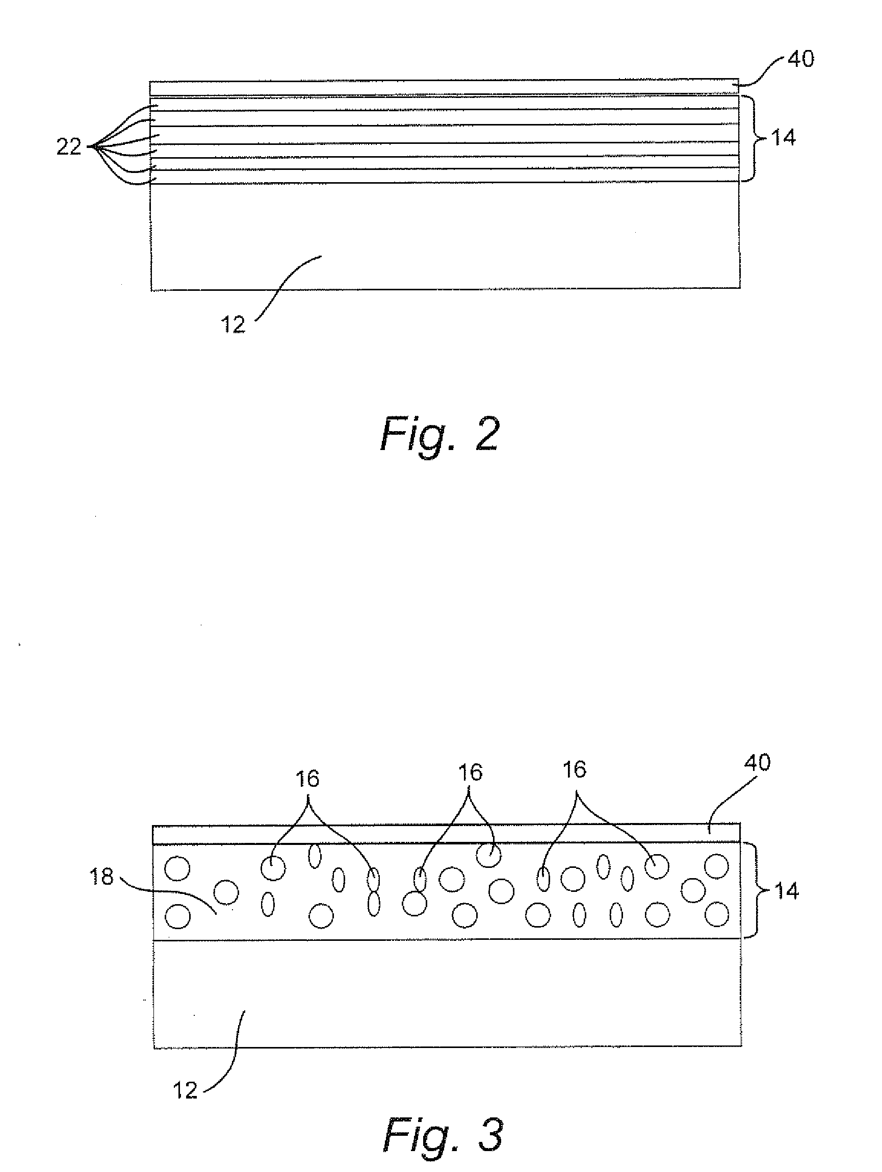
[0020]Several types of damping materials may exist. Natural composites (such as Fe—C—Si and Al—Zn alloys) may use a damping mechanism relating to viscous or plastic flow across phase boundaries between the matrix and the second phase. Ferromagnetic alloys (such as Fe, Co, and Ni, Fe—Cr, Fe—Cr—Al, Co—Ni—Ti, and Co—Ni—Fe) may use a damping mechanism relating to magneto-mechanical static hysteresis due to irreversible movement of ferromagnetic domain-walls. Alloys based on dislocation damping (such as Mg, Mg-0.6% Zr, Mg-Mg2Ni) may use a damping mechanism relating to static hysteresis due to the movement of dislocation loops, breaking away from pinning points. Alloys with movable twin or phase boundaries (such as Mn—Cu, Mn—Cu—Al, Cu—Zn—Al, Cu—Al—Ni, Ti—Ni, and NiTi—Co) may use a damping mechanism relating to the movement of twin boundaries, martensite-martensite boundaries, and boundaries between martensite and the matrix-phase.

[0021]In general, the diversity and ambiguity of damping un...


PUM

PropertyMeasurementUnit
temperaturesaaaaaaaaaa
thicknessaaaaaaaaaa
thicknessaaaaaaaaaa

Abstract

A gas turbine or turbine component partially or fully coated with a damping surface layer. The damping surface layer may have a thickness between 0.1 and 2000 microns and may be capable of dissipating vibration or modifying a resonance frequency of the gas turbine or turbine component at ambient room temperatures including operational temperatures greater than 500° F., and the damping surface layer comprises at least one of (a) at least two layers comprising a first layer of at least one hard material and a second layer comprising at least one soft material, (b) a composite comprising a nickel alloy with a heat softenable chemistry, (c) a fine-grained nickel-based superalloy, or (d) a porous metallic coating, a porous metallic and ceramic coating, or a ceramic coating.

Description

BACKGROUND OF THE INVENTION[0001]The present invention generally relates to turbines and generally relates to surface structures that damp vibration of turbine components.[0002]Operation of a turbine may subject many of the turbine's components to vibrational stresses. Vibrational stresses may shorten the fatigue life of components, thus potentially subjecting them to failure, especially when the components are also subjected to the harsh environment of a gas turbine.[0003]One way to reduce vibrational stresses and extend the life of components may relate to damping the vibration of the component, thus potentially altering vibrational characteristics in such a way to increase its useful life. Mechanical damping mechanisms have been used to damp vibration of turbine components. Examples of the mechanical means include a spring-like damper inserted in a rotor structure beneath the airfoil platform, or a damper included at the airfoil tip shroud.[0004]The phenomenon of damping may gene...

Claims


Application Information

Patent Timeline
Patent Type & Authority Applications(United States)
IPC IPC(8): F01D25/04F01D5/28B23P15/02
CPCC23C28/321C23C30/00C23C28/34C23C28/3455F05D2300/2102F01D5/288C23C28/3215F05D2300/21F05C2201/0466Y10T29/4932C23C28/345F05D2300/133C23C28/42F01D5/26F05D2230/90F05D2260/96
Inventor HARDWICKE, CANAN USLU
Owner GENERAL ELECTRIC CO
Why Eureka
Try Eureka