Sintered gear

Inactive Publication Date: 2009-12-24
MIBA SINTER AUSTRIA
View PDF10 Cites 9 Cited by
  • Summary
  • Abstract
  • Description
  • Claims
  • Application Information

AI Technical Summary

Benefits of technology

[0009]This objective is achieved by the invention on the basis of a sintered gear and the tooth base has a surface which is subjected to a thermo-mechanical finishing process and has a surface roughness with an arithmetical mean roughness value Ra, measured in accordance with DIN EN ISO 4287, which is selected from a range with a lower limit of 0.2 μm and an upper limit of 2.0 μm, and on the basis of a method of producing the sintered gear whereby its tooth base is subjected to thermo-mechanical processing until this surface roughness is imparted to the tooth base. Surprisingly, it has been found that subjecting the tooth base to thermo-mechanical processing improves resistance of the tooth to breaking by avoiding abrasive cracks, and in addition, especially in the event of inadequate cooling of the processed surface, the thermo-mechanical processing of this surface also induces stresses in the tooth base, thereby enabling the internal stress profile in this region and hence the ability of a sintered gear to withstand mechanical stress to be increased. The strength is therefore higher—than sintered gears not subjected to a finishing process—by up to 20%. Due to the internal stress induced by pressure, it is possible to achieve levels of strength close to those which can be obtained from solid material, and in particular, the gap between solid steel gears and gears made from sintered materials, which currently have a 20% lower mechanical strength, can be reduced by up to 10%. With the sintered gear proposed by the invention, strength levels can be achieved which are comparable with those of solid gears, which means that the case width of such sintered gears can be increased. Thermo-mechanical processing with inadequate cooling likewise leads to a plasto-mechanical hardening of the peripheral layer, as a result of which the porosity in these peripheral layers can also be reduced. This means that an additional surface compaction can be achieved and, generally, that a surface compaction can be applied if this has not been done prior to the thermo-mechanical finishing process. This finishing process also enables the accuracy of the tooth geometry to be increased, thereby reducing the play between mutually meshing gears and hence also improving the acoustic properties of such a transmission, i.e. imparting a low noise level. Another advantage is the fact that due to “strain hardening”, the temperature stress in this surface region is relatively low, which means that re-crystallisation does not occur and there is therefore no drop in stress. With this method, it also possible to reduce the cost of manufacturing such sintered gears because the standard process of irradiating this surface that has been used to date can be dispensed with. This finishing process also reduces flitter caused by the process of rolling the tooth flanks. At the same time, any brittle hard layers can be removed from the surface if necessary.
[0011]In order to increase mechanical strength and further improve acoustic values, it is of advantage if the surface of the tooth base of the sintered gear has a maximum roughness profile value R3z, measured in accordance with DBN 31007, which is selected from a range with a lower limit of 0.5 μm and an upper limit of 8 μm.
[0013]In terms of improving ability to withstand stress and increasing the service life of the sintered gear, it is also of advantage if the tooth base superficially has at least the same hardness as the surface of the adjoining tooth flanks and the adjoining rounded regions of the transitions to the tooth flanks.
[0014]In one embodiment of the sintered gear, the surface of the tooth base has a residual porosity of at most 12%. Surprisingly, it has been found that such a low residual porosity still assists lubrication of a geared transmission with a sintered gear proposed by the invention to a sufficient degree that, in conjunction with the improved ability to withstand mechanical stress, i.e. the strength of the sintered gear, the service life itself can be further improved.
[0016]In this connection, it is also of advantage if the finishing process is conducted with a polishing means with a grain size selected from a range with a lower limit of 70 and an upper limit of 110, and has a grain size of 90.

Problems solved by technology

Due to the manufacturing method, however, sintered components do not have high strength unless treated, due to the residual porosity of these sintered components.
This reduces fatigue notch sensitivity in the tooth base region and increases the bearing capacity of the gear.

Method used


Image

  • Sintered gear
  • Sintered gear

Examples


example 1

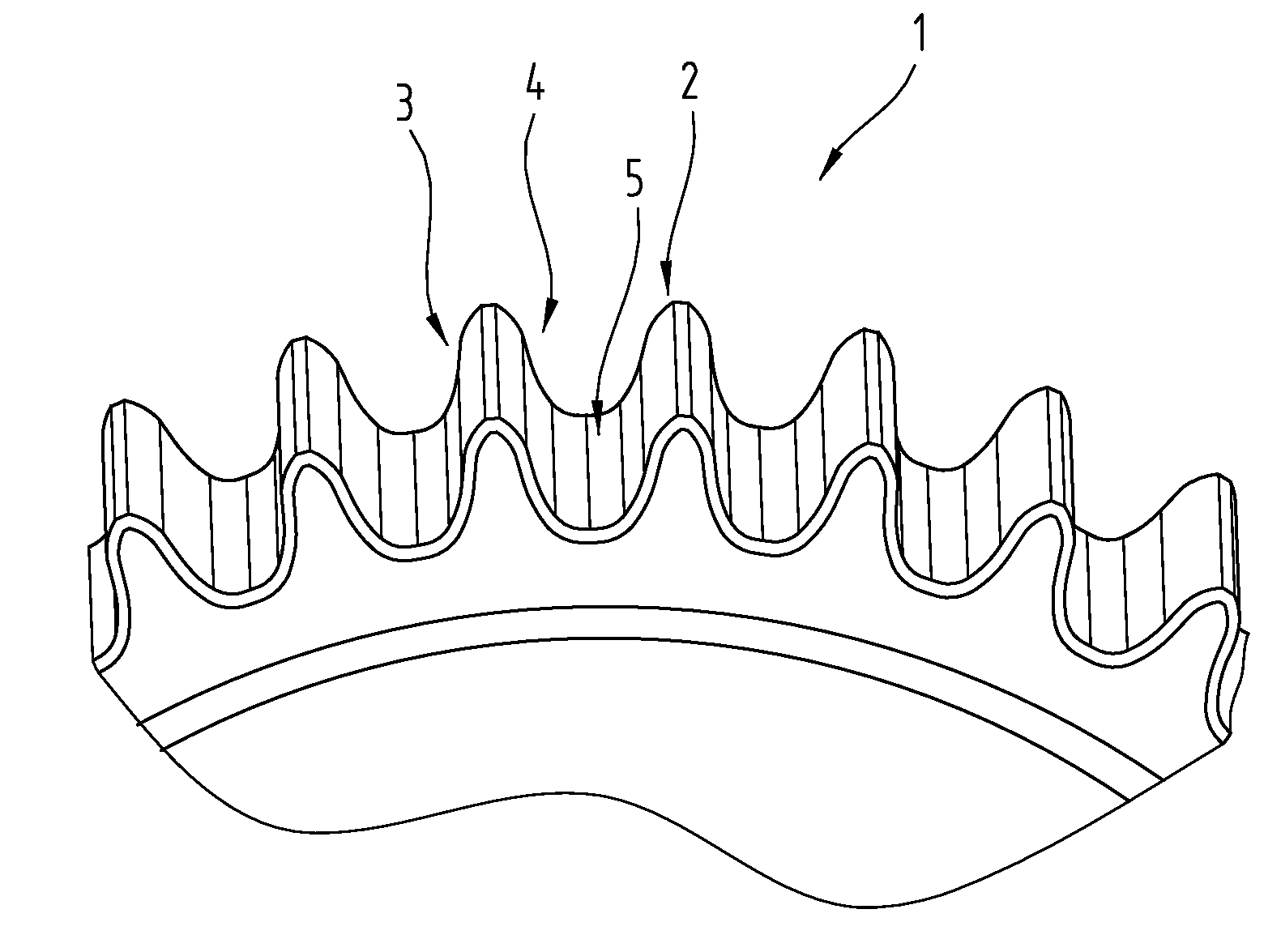
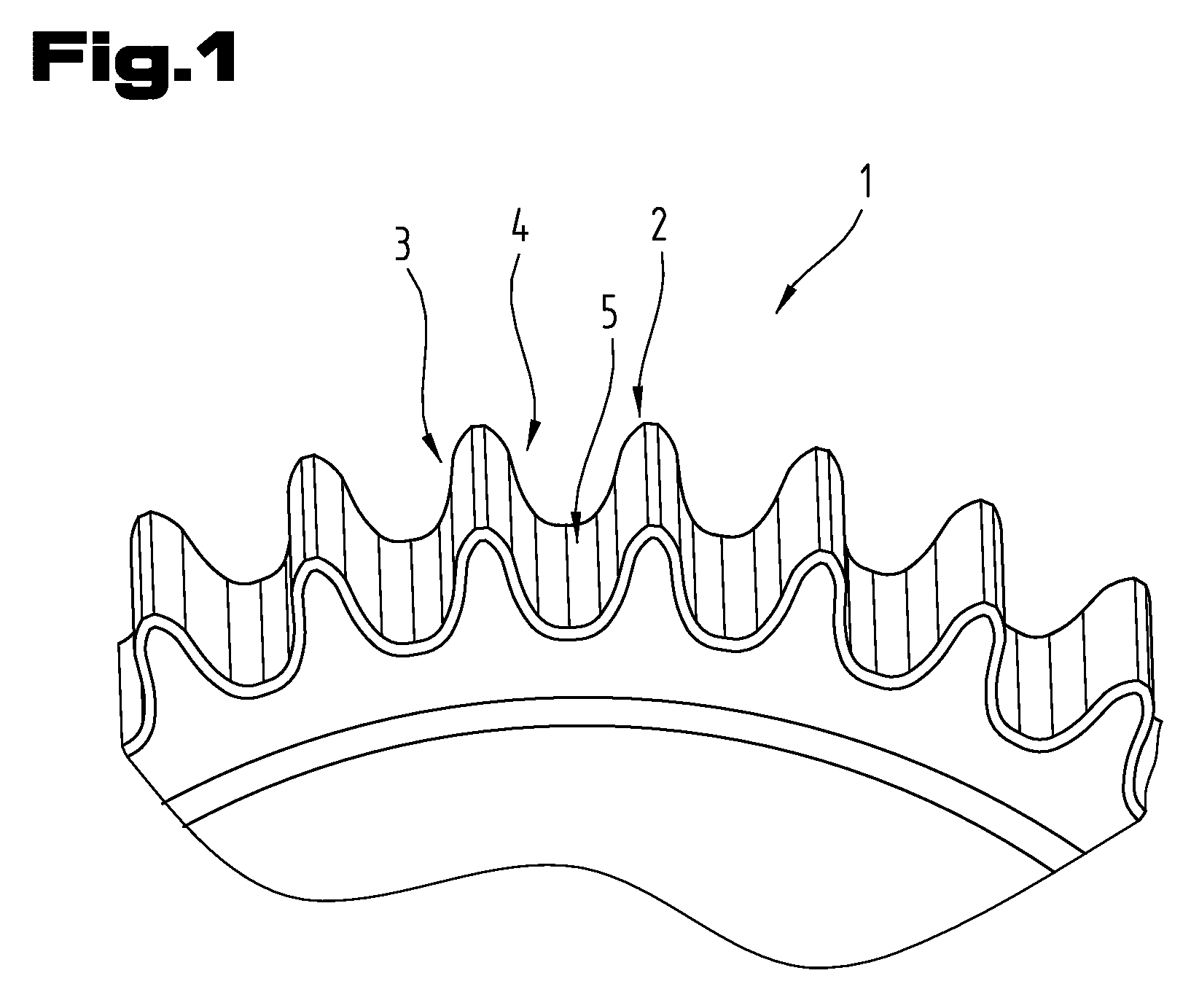
[0032]An alloy powder of the following composition was used to produce a sintered gear 1 as proposed by the invention:

[0033]carbon 0.2% by weight, magnesium <0.1% by weight, molybdenum 0.85% by weight, the rest being iron with impurities induced by the manufacturing process.

[0034]This alloy powder was compacted at a pressure of 700 MPa to obtain a green compact and then sintered at a temperature in the range of between 1100° C. and 1350° C. This was followed by a calibration of the sintered gear 1 with the aid of a die by pressing it through the die.

[0035]As an alternative to pushing it through the die, the component may be ejected from the die in the direction in which it was introduced into it.

[0036]The resultant sintered gear 1 had a core density of ca. 6.9 g / cm3 and a surface density greater than 7.4 g / cm3.

[0037]It should be pointed out that the entire sintered gear 1 may be of approximately the core density if processing a non-compacted material.

[0038]Following the surface comp...

example 2

[0042]A sintered gear 1 was produced in the same way as explained in connection with example 1, care being taken to ensure that the surface of the tooth flanks 3, 4 and the tooth base 5 were of approximately the same hardness. This hardness was between 650 HV0.1 and 870 HV0.1. The pulsator test produced the same ratios as those given in example 1.

[0043]Both the sintered gear 1 based on example 1 and that based on example 2 had a residual porosity of max. 12% in the region of the surface of the tooth flanks 3, 4 and the tooth base. In particular, the residual porosity in example 1 was 5.1% and that based on example 2 was 4.5%.

example 3

[0044]Example 1 was essentially repeated and a grinding means with a grain size of 90 was used so that the surface of the tooth base 5 had a max. roughness profile value R3z, measured in accordance with DBN 31007, of 4.2 μm. The pulsator test produced the same ratios as specified in example 1.

OTHER EXAMPLES

[0045]Example 1 was repeated several times but the surface roughness was varied within ranges of 0.2 μm to 3.0 μm and the max. roughness profile value was varied within ranges of 0.3 μm to 15 μm. Results showed that particularly good ability to withstand mechanical stress was obtained in the ranges from 0.2 um to 2.0 μm for Ra and from 0.5 μm to 8 μm for R3z.

[0046]In addition to increasing strength, the method proposed by the invention has a side-effect in that toothing errors caused by the manufacturing process can be at least largely compensated.

[0047]The thermo-mechanical finishing process subjects the surface to a temperature stress selected from a range with a lower limit of ...


PUM

PropertyMeasurementUnit
Lengthaaaaaaaaaa
Lengthaaaaaaaaaa
Porosityaaaaaaaaaa

Abstract

The invention relates to a sintered gear (1) with teeth (2), between which a tooth base (5) is respectively formed. The tooth base (5) has a surface which is subjected to a thermo-mechanical finishing process and a surface roughness with an arithmetical mean roughness value Ra, measured in accordance with DIN EN ISO 4287, selected from a range with a lower limit of 0.2 μm and an upper limit of 2.0 μm.

Description

BACKGROUND OF THE INVENTION[0001]The invention relates to a sintered gear with teeth, between which a tooth base is respectively formed, as well as a method of producing the sintered gear with improved ability to withstand mechanical stress.[0002]It is becoming increasingly common for components manufactured by means of conventional molten metallurgical methods to be replaced by components made by powder metallurgy, not least because they are easier to produce in more complex geometries. Due to the manufacturing method, however, sintered components do not have high strength unless treated, due to the residual porosity of these sintered components. In one respect, this residual porosity is desired, for example in the case of sintered components intended for use in lubricated systems, in which case the pores can be used as reservoirs for lubricant. Various methods of reducing this residual porosity have already been proposed in the prior art as a means of improving ability to withstan...

Claims


Application Information

Patent Timeline
IPC IPC(8): B32B3/02B21K1/30B24B1/00
CPCB22F3/24Y10T428/211B22F2003/241B22F2003/247B22F2003/248B22F2998/10C22C33/0257F16H55/06B22F5/08Y10T29/49467B22F3/02B22F3/10B22F3/164
Inventor SCHMID, HERBERTDICKINGER, KARLSIESSL, WOLFGANG
Owner MIBA SINTER AUSTRIA
Why Eureka
Try Eureka