LED driving circuit, LED driving control unit and transistor switch module thereof

a technology of led driving circuit and led driving control unit, which is applied in the direction of electric variable regulation, process and machine control, instruments, etc., can solve the problems of increased gate-source capacitance (cgs), increased production cost, and increased power consumption of mosfet with better high voltage withstanding capability, so as to reduce the requirement on the withstand voltage of mosfet and reduce the power consumption of mosfet. , the effect of significantly reducing the cost of led

Active Publication Date: 2009-12-31
GREEN SOLUTION TECH CO LTD
View PDF4 Cites 62 Cited by
  • Summary
  • Abstract
  • Description
  • Claims
  • Application Information

AI Technical Summary

Benefits of technology

[0006]In view of the aforementioned issues, as the dimming representing the OFF state, the present invention maintains the current of the LED module at a very small magnitude, or clamps the voltage difference between the drain and source of the transistor coupled to the LED module within a preset value; accordingly, the cross voltage over the LED module can be kept approximately at a lighting threshold voltage, such that the voltage between the drain and source of the transistor coupled to the LED module will not become excessively large. Therefore, the LED driving circuit and LED driving control unit thereof according to the present invention allows to reduce the requirement on the withstand voltage of MOSFET, and the cost of the LED driving circuit can be significantly lessened, further decreasing power consumption of the MOSFET and improving integral efficiency of the circuit.

Problems solved by technology

The high voltage MOSFET can withstand high voltage, whereas occupies comparatively larger chip area, resulting in more production cost and significantly increases the gate-source capacitance (Cgs) as well.
Consequently, the MOSFET having better high voltage withstanding capability consumes more power, and additional circuits are needed for heat sinking so as to prevent possible over-temperature or damage problems in the circuit and MOSFET.

Method used


Image

  • LED driving circuit, LED driving control unit and transistor switch module thereof
  • LED driving circuit, LED driving control unit and transistor switch module thereof
  • LED driving circuit, LED driving control unit and transistor switch module thereof

Examples


Embodiment Construction

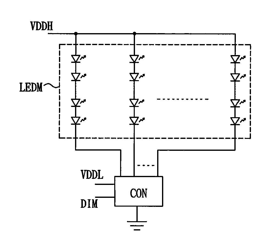
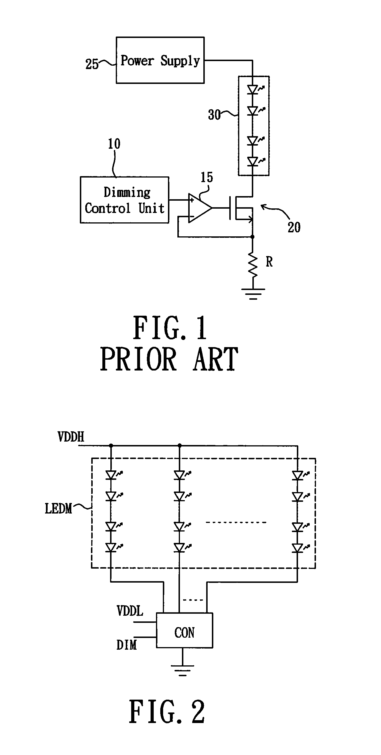
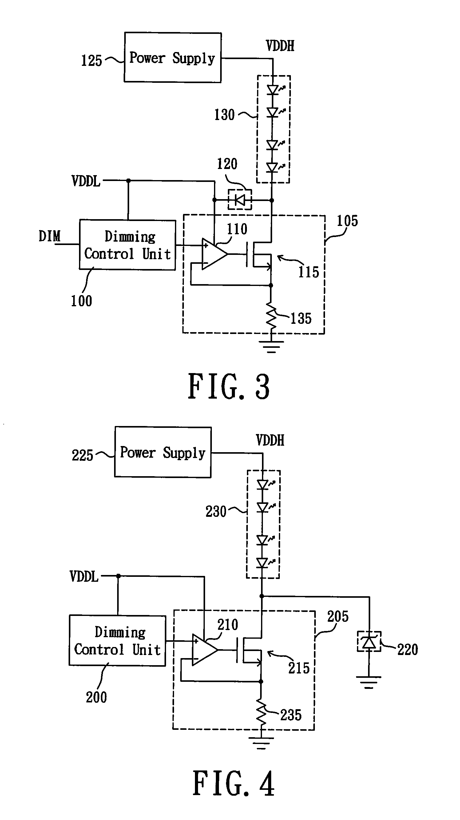
[0026]In order to prevent occurrence of excessive cross voltage of the transistor controlling the current flowing through a LED module during a dimming process of the LED module, the present invention switches the current flowing through the LED module between an operating current value and a maintaining current value, wherein the maintaining current value is much smaller than the operating current value; e.g., the ratio of the operating current value against the maintaining current value being greater than 100. Alternatively, the present invention may use a voltage clamping component to, as the MOSFET coupled to the LED module being in a cut-off state, clamp the electric potential at the drain of the MOSFET so as to reduce requirement on the withstand voltage of the MOSFET. In this way, the precision of dimming operations can be sustained, and problems of expensive fabrication cost and high power consumption caused by use of high withstand voltage transistors can be effectively res...


PUM


Abstract

An LED driving circuit is used for dimming by switching between an operating current and a maintaining current or by voltage clamping of a source/drain of MOSFET that is coupled to the LED module. When the LED module is dimmed off, the voltage across the LED module can be kept at a value around a lighting threshold voltage of the LED module that is a minimum voltage for lighting the LED module. Therefore, a voltage difference between the drain and the source of MOSFET coupled to the LED module is smaller than that in the conventional arts. Hence, a withstand voltage of MOSFET can be reduced, and cost of the LED driving circuit as well as the power consumption of MOSFET can be lessened, thereby improving integral efficiency of the circuit.

Description

BACKGROUND OF THE INVENTION[0001]1. Field of the Invention[0002]The present invention relates to a Light-Emitting Diode (LED) driving circuit and LED driving control unit thereof; in particular, the present invention relates to an LED driving circuit and LED driving control unit for maintaining small amount of current and clamping voltage of the LED driving circuit.[0003]2. Description of Related Art[0004]Refer first to FIG. 1, wherein a conventional Light-Emitting Diode (LED) driving device is shown. The illustrated LED driving device comprises a dimming control unit 10, an error amplifier 15, an N-type Metal Oxide Semiconductor Field Effect Transistor (MOSFET) 20, a power supply 25, an LED module 30, and a current detection resistor R. The power supply 25 is coupled to one end of the LED module 30 so as to provide a driving voltage enabling the LED module 30 lighting. The N-type MOSFET 20 is coupled to the other end of the LED module 30, which controls the magnitude of current flo...

Claims


Application Information

Patent Timeline
Patent Type & Authority Applications(United States)
IPC IPC(8): H05B37/02
CPCH05B33/0845H05B45/10H05B45/395H05B45/46Y02B20/30
Inventor SHIU, SHIAN-SUNGYU, CHUNG-CHELIU, JUANJUAN
Owner GREEN SOLUTION TECH CO LTD
Why Eureka
Try Eureka