Optical measurement apparatus and optical measurement method for a liquid or molten material

a technology of optical measurement apparatus and which is applied in the direction of measurement devices, instruments, phase-affecting properties, etc., can solve the problems of the optical measurement of a liquid or molten material is involved, and the vibration or ruffling of the measuring surface, which have been required to be solved, etc., to prevent the reduction of measurement accuracy, the effect of stably measuring and generating a specular surfa

Active Publication Date: 2009-12-31
NAT INST OF ADVANCED IND SCI & TECH +1
View PDF5 Cites 4 Cited by
  • Summary
  • Abstract
  • Description
  • Claims
  • Application Information

AI Technical Summary

Benefits of technology

[0019]According to the present invention, in the optical measurement of a liquid or molten material, the measuring surface is set at a bottom face of the liquid or molten material as a to-be-measured object, to thereby readily generate a flat specular surface that can be stably measured. Further, the measurement at the bottom face of the liquid or molten material can realize a flat face at the bottom face of a transparent container, thereby eliminating the need for a large amount of the to-be-measured material. Furthermore, the liquid or molten material is prevented from causing a reaction with oxygen or nitrogen remaining in the container. Resultantly, many advantages are provided, such as prevention of lowering of the measurement accuracy.
[0020]According to the measurement apparatus and the measurement method of the present invention, a flat part of a bottom face of a transparent container can be used as an optical measuring surface, to thereby effectively measure even a small amount of the measurement object material. Further, the material is sealed in a transparent and resistant container and the inside of the container can be vacuumized or sealed with an inactive gas. This consequently prevents the liquid or molten-state material from evaporating or causing a reaction with other substances such as oxygen or nitrogen. Furthermore, by allowing the container to contain therein, together with the measurement object material, a substance (e.g., titanium) that more easily reacts with other substance than the material as a measurement object and that has a melting point higher than that of the material, such a substance can be disposed while being easily separated from the material as a measurement object, thus realizing a stable optical measurement of the liquid or molten material at low cost.

Problems solved by technology

As described above, although the optical measurement of a liquid or molten material has advantages not achievable by other mechanical measurements, the optical measurement of a liquid or molten material is involved with disadvantages such as the vibration or ruffling of the measuring surface, which have been required to be solved.
In particular, in the case of a measurement at high temperature, another new disadvantage different from the above ones also appears remarkably.
For example, there is a disadvantage due to evaporation.
Specifically, due to the evaporation at a temperature higher than the boiling point as well as a strongly decrease in mass of the substance, such disadvantages are caused as dissipation of the material and contamination of the measurement apparatus due to the evaporated substance.
Chemical reaction also comes to be a significant disadvantage.
Some disadvantages have been also pointed out, with regard to the optical constant measurement method of a high-temperature material, according to Journal of Non-Crystalline Solids, vol.
This limits measurement objects to very special materials.
However, unlike a solid matter, a molten material tends to have a round surface due to the surface tension.
However, a material to be used for, for example, data storage and an accumulation medium, is unstable at high temperature and is relatively high cost.
Therefore, the above method and apparatus are disadvantageous in the application scope and cost.

Method used


Image

  • Optical measurement apparatus and optical measurement method for a liquid or molten material
  • Optical measurement apparatus and optical measurement method for a liquid or molten material
  • Optical measurement apparatus and optical measurement method for a liquid or molten material

Examples


embodiment 1

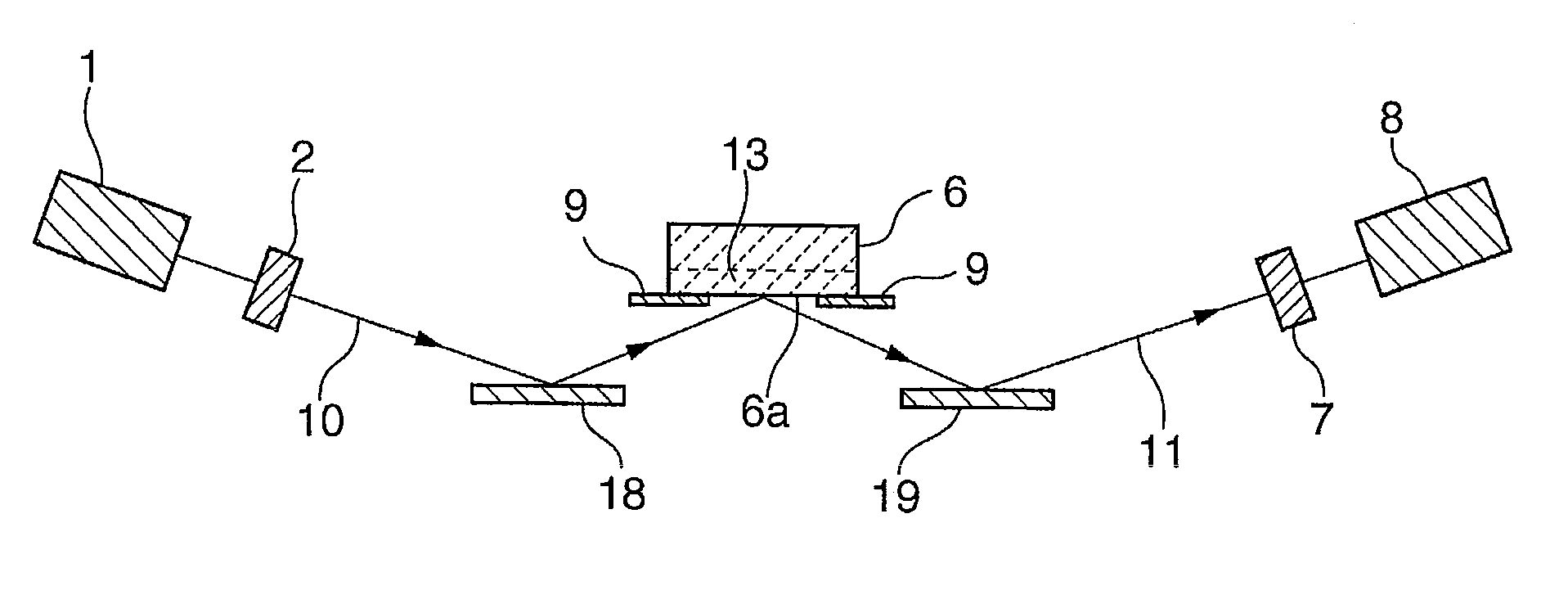
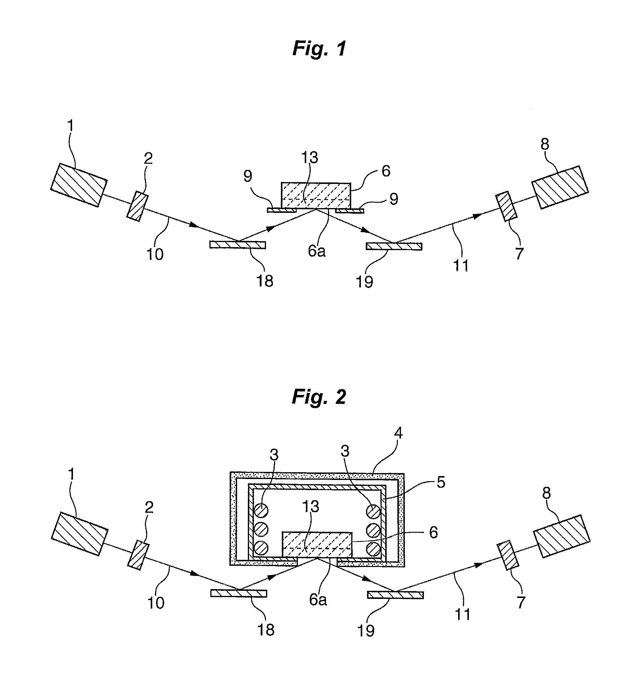
[0030]FIG. 1 is a schematic side cross-sectional view illustrating an optical measurement apparatus of a liquid or molten material according to Embodiment 1 of the present invention. In the optical measurement apparatus of Embodiment 1, the measurement of a refractive index of the molten material using ellipsometry will be described as a main measurement item, but the present invention may also be applied not only to the measurement of a refractive index but also to other measurements of an optical constant, such as a measurement of a reflectivity or a measurement of an optical absorptance, in the similar manner.

[0031]A transparent container 6 for containing therein a liquid or molten material 13 is entirely formed of a transparent material in Embodiment 1, and the bottom of the container has a bottom face 6a of a flat face having smoothness required for an optical measurement. The container 6 is made of a material that does not alter the to-be-measured material and that is resistan...

modification example 1

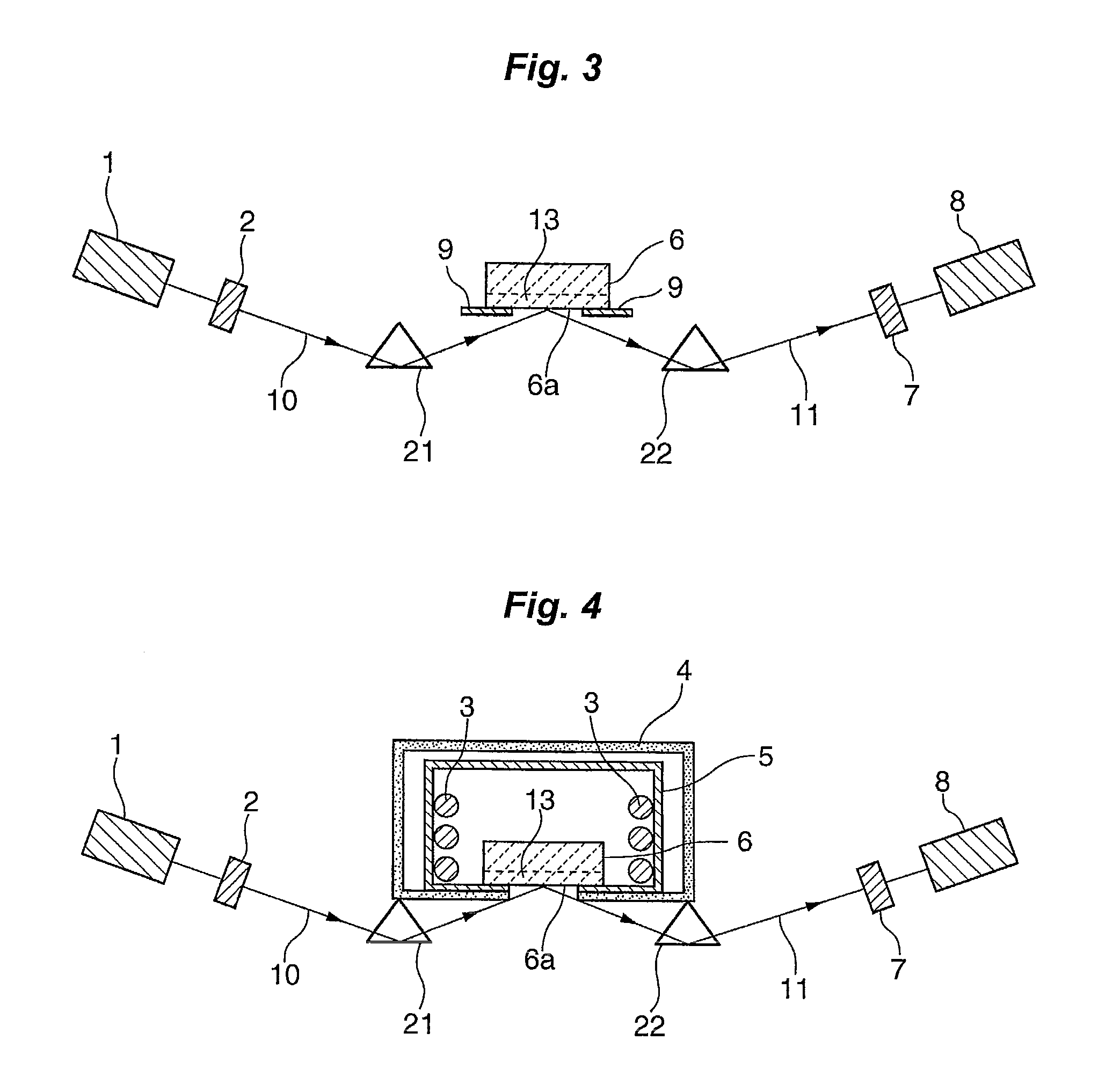
[0039]A noble metal mirror body made of gold, platinum or the like, is stable in the air, and has a favorable light reflectivity. However, such a noble metal mirror body is prepared for an exclusive use through a special manufacture process, and thus requires a high cost. To solve this, in Modification Example 1 of Embodiment 1, a configuration as shown in FIG. 3 is used where prisms 21 and 22 are used as the optical-path-redirecting means instead of the mirror. The total (internal) reflection properties of these prisms 21 and 22 are utilized to provide the same optical-path-redirecting action as that by the mirror. In the case of the prisms 21 and 22, the incident light 10 is caused to enter the bottom face 6a of the container 6 without losing the information thereof, and the reflected light 11 also can be guided to the photodetector 8 while retaining the information thereof. Although the information of light may be changed in some cases, the information of light is changed with re...

modification example 2

[0043]In Modification Example 2 of Embodiment 1, when the molten material 13 is sealed in the container 6, it is possible to contain in the inside of the container together with an inactive gas, without using vacuumization. In this case, the inside of the container is vacuumized in advance, and then the inactive gas is introduced in the container. Generally, inactive gases do not decompose or cause reaction with other substances. Thus, no risk is caused where the molten material 13 reacts with the inactive gas to alter or be changed into another substance. Examples of the inactive gas that can be used include helium, argon, xenon, krypton, or the like, but among which argon is most preferable from the viewpoints of availability and cost.


PUM

PropertyMeasurementUnit
temperatureaaaaaaaaaa
wavelengthaaaaaaaaaa

Abstract

An apparatus for optical measurement of a liquid or molten material, which has: a transparent container which has a bottom face and is capable of containing a to-be-measured material therein, with the bottom face at least having a flat face and being transparent; and an optical device that irradiates a light to the bottom face of the container and that detects and measures a reflected light from the bottom face; and a method for optically measuring a liquid or molten material using the apparatus.

Description

FIELD OF THE INVENTION[0001]The present invention relates to an optical measurement apparatus and an optical measurement method for a liquid or molten material. In particular, the present invention relates to an apparatus for optically measuring a liquid or molten material, and to a noncontact optical measurement method for a molten material, in each of which method and apparatus light is irradiated to the liquid or molten material, to thereby measure physical properties, such as refractive index, reflectivity, or absorptance, of the material.BACKGROUND OF THE INVENTION[0002]In recent years, physical properties of a liquid or molten material are utilized in various fields. For example, in data storage and accumulation fields, such as an optical disk and a phase-change memory, the material is used that is obtained by heating a raw material to thereby melt and then solidify it. In a refining process, the material is directly melted at high temperature, to thereby manufacture a steel p...

Claims


Application Information

Patent Timeline
Patent Type & Authority Applications(United States)
IPC IPC(8): G01N21/55G01N21/41G01N21/47G01N21/59
CPCG01N21/0332G01N21/211G01N2201/0231G01N2201/023G01N2201/0227
Inventor KUWAHARA, MASASHIFUKAYA, TOSHIOSHIMA, TAKAYUKITOMINAGA, JUNJIENDO, RIESUSA, MASAHIROSUZUKI, MICHIOTSUTSUMI, KOICHI
Owner NAT INST OF ADVANCED IND SCI & TECH
Why Eureka
Try Eureka