
Magnetic particle holding carrier and method for preparing the same

Inactive Publication Date: 2009-12-31
NAT UNIV CORP TOKYO UNIV OF AGRI & TECH +1
View PDF0 Cites 25 Cited by
  • Summary
  • Abstract
  • Description
  • Claims
  • Application Information

AI Technical Summary

Benefits of technology

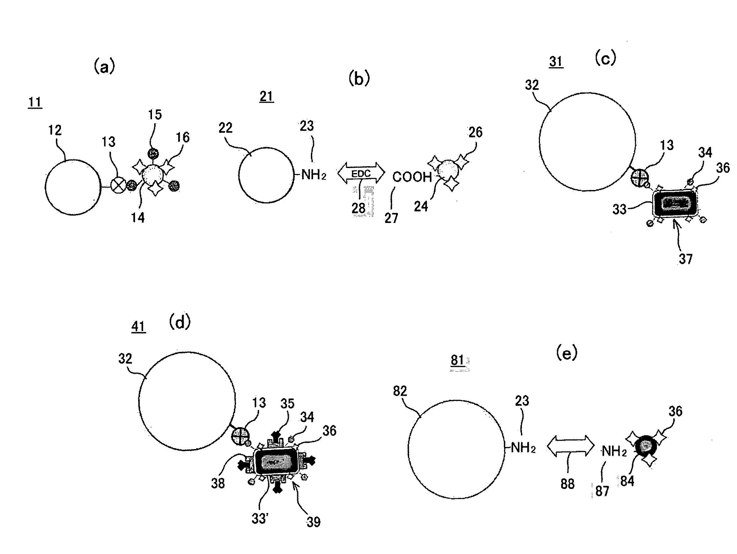
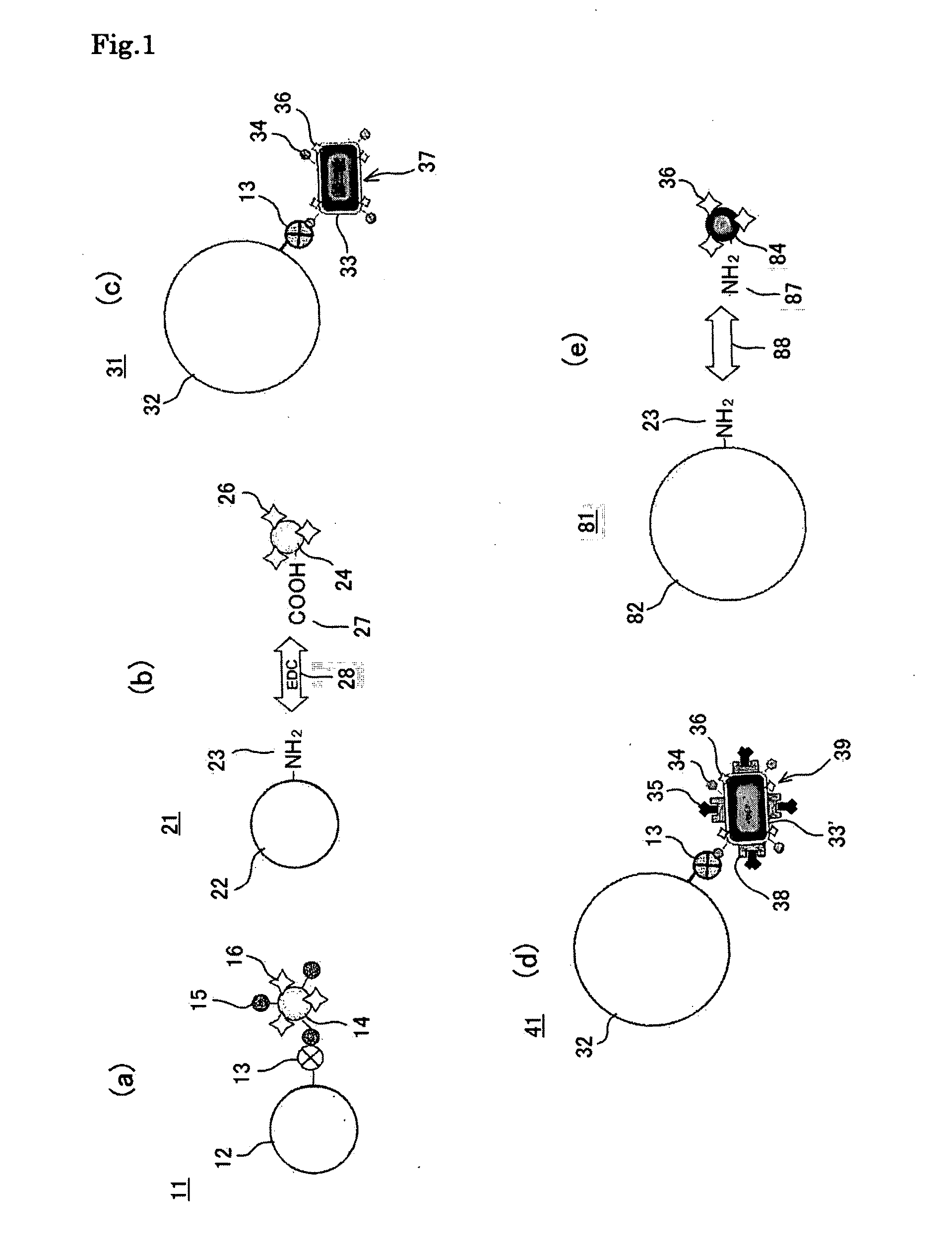
[0027]The present inventors made it possible to automatize a treatment with respect to nano-size magnetic particles much easier by fitting nano-size magnetic particles (about 1 nm to several 100 nm) such as bacterial magnetic particles produced by a magnetic bacterium, to a particulate carrier having a size on the order of micrometer (ranging from about 1 μm to several 100 μm) in accordance with the purpose of the treatment.

Problems solved by technology

However, the type of the functional protein is limited to an antibody, Protein A, Protein G, streptavidin and so forth.
Such a complicated operation must be sometimes performed.
However, in general, it is difficult to magnetically control nano-size magnetic particles in liquid.
As a result, separation may not be performed quickly.
In addition, since nonspecific adsorption of bacterial magnetic particles to the inner wall of a tip occurs during the separation, resuspension efficiency may further decrease.
However, it was very difficult to define conditions for obtaining a stable magnetic separation rate.
Since conditions such as the size of bacterial magnetic particles, etc., strength of magnetic force and magnetism are fixed, when a preparation substance such as a protein using bacterial magnetic particles is subjected to a treatment including separation, extraction and resuspension using a magnetic field or a filter, satisfactory results are not always obtained with respect to automatization, efficiency, handleability, diversification and quickness depending upon the purpose of treatment.
In particular, in the case where separation and extraction are performed by applying a magnetic field to aggregate bacterial magnetic particles and thereafter the magnetic field is removed as mentioned above, it is difficult to release the aggregation of particles and resuspend the particles in a solution by simple removal of the magnetic field.
In this case, it is difficult to attain automatization and satisfy efficiency, etc.

Method used


Image

  • Magnetic particle holding carrier and method for preparing the same
  • Magnetic particle holding carrier and method for preparing the same
  • Magnetic particle holding carrier and method for preparing the same

Examples


experiment 1

[Experiment 1]

[0112]Immunoassay for detecting a prostate specific antigen (PSA) using a magnetic particle holding carrier according to an embodiment of the present invention is prepared (manually performed).

[0113](1) Study on the Concentration of Antibody Immobilized onto the Bacterial Magnetic Particles (BMPs)

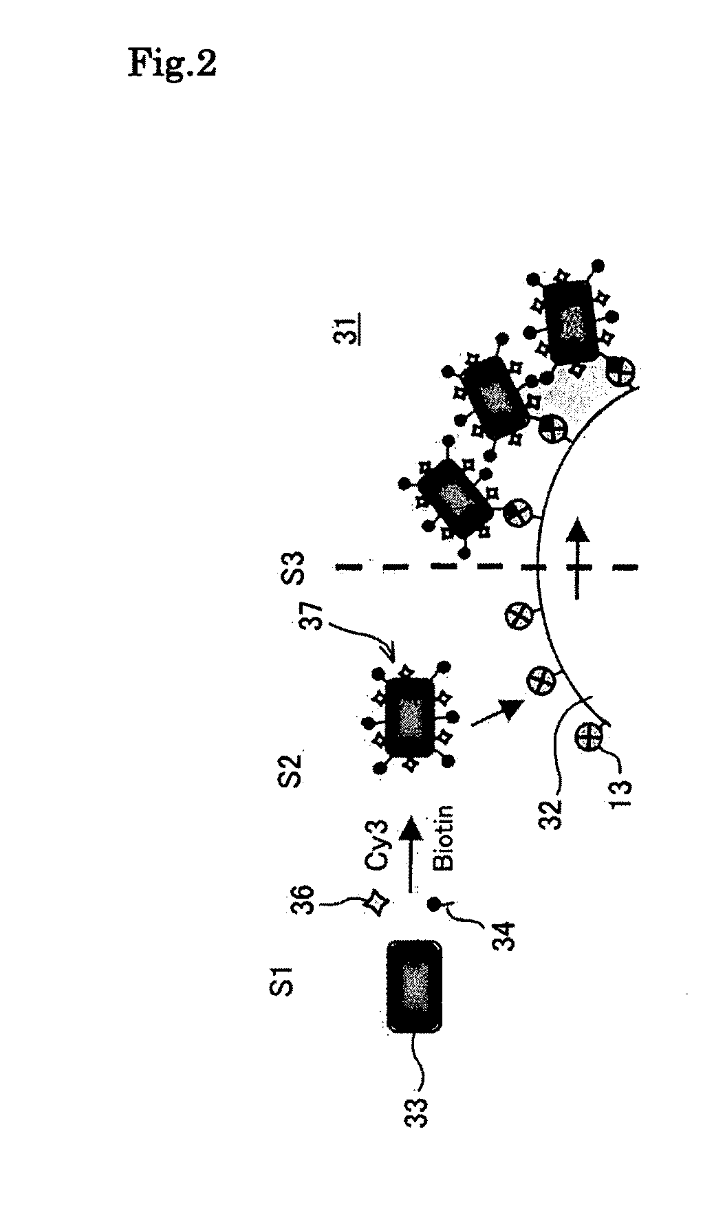
[0114]In a step 41 of FIG. 11, the bacterial magnetic particles 33′ (ZZ-BMPs) displaying ZZ domains 38, which are an IgG binding sites of Protein A and obtained from a ZZ domain expressing strain were labeled with the fluorescent dye 36 (Cy3) and biotin 34. In a step S42, to 20 μg of the biotin / fluorescent dye-introduced bacterial magnetic particles 37′ (Cy3-[ZZ-BMP]-biotin), solutions of mouse-derived anti-human PSA antibody 60 (IgG2a) different in concentration (0 to 60 μg / ml, 20 μl) were added and incubation was performed while stirring at room temperature for one hour to immobilize the antibody 60. The antibody-immobilized biotin / fluorescent dye-introduced bacterial magnet...

experiment 2

[Experiment 2]

[0128]The magnetic particle holding carrier is stable during magnetic separation process carried out in the magnetic particle holding carrier treatment apparatus as described below.

[0129]A suspension solution (50 μg / ml, 2 ml) of biotin / fluorescent dye-introduced bacterial magnetic particles 37 (Cy3-BMP-biotin) was added to a suspension solution (3.0×10⁶ beads / ml, 10 ml) of the streptavidin-labeled polystyrene beads, which were micro-size (5 μm in diameter herein) polystyrene beads whose surfaces were coated with streptavidin 13 serving as a receptor and which served as a particulate carrier 32. A reaction was performed for 15 minutes while maintaining a dispersion state by pipetting. This operation was repeated 10 times to prepare the magnetic particle holding carrier 31 according to the third embodiment of the present invention.

[0130]Subsequently, using the magnetic particle holding carrier 31, the stability of the biotin / fluorescent dye-introduced bacterial magnetic ...

experiment 3

[Experiment 3]

[0134]Next, the magnetic separation ratio of the magnetic particle holding carrier by the magnetic particle holding carrier treatment apparatus (full automatic immunoassay apparatus SX-8PC) is evaluated. The magnetic particle holding carrier 31 was magnetically separated and resuspended repeatedly (1 to 5 times) in the same manner as in Experiment 1 and transferred to the well 71b in the next step. At that time, the concentration of the magnetic particle holding carrier 31 was measured. At this time, the number of the beads of the magnetic particle holding carrier 31 before magnetic separation was set at 1.0×10⁷. As a buffer solution for suspending the magnetic particle holding carrier 31, PBS (2001) containing 0.05% nonionic surfactant, Adekanol (ADK) was used. The magnetic separation rate was obtained based on the following equation:

Magnetic separation rate=concentration of the beads of magnetic particle holding carrier after magnetic separation / concentration of the ...


PUM

PropertyMeasurementUnit
Magnetismaaaaaaaaaa
Dispersibilityaaaaaaaaaa
Covalent bondaaaaaaaaaa

Abstract

Provided is a magnetic particle holding carrier enabling automatization of treatment of a biological substance such as a protein by improving dispersibility of nano-size magnetic particles and suppressing nonspecific adsorption onto the wall of a container such as a pipette tip without damaging the properties of the nano-size magnetic particles such as a large solid-phase area and ability to arbitrarily design a functional protein, and provide a method for preparing the same. The magnetic particle holding carrier is formed of a micro-size nonmagnetic carrier and a plurality of nano-size magnetic particles bound to the carrier.

Description

TECHNICAL FIELD[0001]The present invention relates to a magnetic particle holding carrier and a method for preparing the same.BACKGROUND ART[0002]In conventional techniques for analyzing and treating biological substances such as DNA and proteins, a biological substance is held on magnetic or nonmagnetic particles, which have a large solid-phase surface per volume compared to other solid-phase carriers such as a microtiter plate, mixed in a solution containing a target biological substance and suspended to detect, separate, isolate and extract the target biological substance by use of a high reactivity and encounter probability thereof. Particularly, magnetic particles are an excellent solid-phase carrier having various advantages. For example, they can be easily and quickly collected by external application of a magnetic field, and therefore centrifugation and filtration steps can be removed. Because of such an advantage, magnetic particles can contribute to automatization of a who...

Claims


Application Information

Patent Timeline
IPC IPC(8): C12N11/16B05D5/12B05D1/04
CPCG01N33/54333C07K17/14
Inventor MATSUNAGA, TADASHITAKEYAMA, HARUKOYOSHINO, TOMOKOTAJIMA, HIDEJI
Owner NAT UNIV CORP TOKYO UNIV OF AGRI & TECH
Learn More