Nano graphene platelet-based conductive inks

Inactive Publication Date: 2010-01-07
GLOBAL GRAPHENE GRP INC
10 Cites 226 Cited by

AI-Extracted Technical Summary

Problems solved by technology

This is on top of the fact tha...

Method used

[0042]The second step comprises dispersing laminar materials (e.g., graphite or graphite oxide particles) in a liquid medium (e.g., water, alcohol, or acetone) to obtain a suspension or slurry with the particles being suspended in the liquid medium. The third step entails subjecting the suspension to direct ultrasonication at a temperature typically between 0° C. and 100° C. Hence, this method obviates the need or possibility to expose the graphite material to a high-temperature, oxidizing environment. Preferably, a dispersing agent or surfactant is used to help uniformly disperse particles in the liquid medium. Most importantly, we have surprisingly found that the dispersing agent or surfactant facilitates the exfoliation and separation of the laminar graphite material. Under comparable processing conditions, a graphite sample containing a surfactant usually results in much thinner platelets compared to a sample containing no surfactant. It also takes a shorter length of time for a surfactant-containing suspension to achieve a desired platelet dimension.
[0045]Oxidized NGPs or graphite oxide platelets may be obtained by intercalation and exfoliation of graphite. Intercalation of graphite to form a graphite intercalation compound (GIC) is well-known in the art. A wide range of intercalants have been used; e.g., (a) a solution of sulfuric acid or sulfuric-phosphoric acid mixture, and an oxidizing agent such as hydrogen peroxide and nitric acid and (b) mixtures of sulfuric acid, nitric acid, and manganese permanganate at various proportions. Typical intercalation times are between one hour and five days. The resulting acid-intercalated graphite may be subjected to repeated washing and neutralizing steps to produce a laminar compound that is essentially graphite oxide. In other words, graphite oxide can be readily produced from acid intercalation of graphite flakes.
[0046]Conventional exfoliation processes for producing graphite worms (interconnected networks of thin graphite flakes) from a graphite material normally include exposing a graphite intercalation compound (GIC) or oxidized graphite to a high temperature environment, most typically between 850 and 1,050° C. These high temperatures were utilized with the purpose of maximizing the expansion of graphite crystallites along the c-axis direction. In some cases, separated NGPs are readily obtained with this treatment, particularly when the graphite has been heavily oxidized. In other cases, the exfoliated product may be subjected to a subsequent mechanical shearing treatment, such as ball milling, air milling, rotating-blade shearing, or...

Benefits of technology

[0027]The presently invented conductive ink is preferably inkjet printable since inkjet printing is a cost-effective way to achieve patterns of various materials on both rigid and flexible substrates. Inkjet printing of electrically conductive nano particle-based inks offer a very practical platform for generating electrical components, such as electrodes and interconnects. More preferably, inkjet printing is conducted using a conventional, inexpensive printhead in a common desk-top printer. This type of printer typically requires the viscosity of the ink to be in the range of 3-30 mPa·S (centi-poise or cP). It is of significance to note that the viscosity of a CNT-based ink can not be in this useful range unless the CNT proportion is exceedingly low. For instance, the CNT concentration of the ink used by Song, et al. [Ref. 1] was as low as 20 μg/mL (approximately 0.002% by weight of CNTs in water). With such a low concentration, it would take several repeated printing passes (overwrites) to achieve a desired CNT amount, thickness, or property; e.g., it took 8 overwrites to achieve a sheet resistivity of 20 μΩm [FIG. 5 in Ref. 1]. By contrast, with the presently invented NGP-based ink that can carry a high NGP proportion, yet still maintaining a relatively low viscosity, one or two printing passes are sufficient to attain the same desired properties achieved with 5-20 overwrites using CNT-based inks. This implies that the printing speed of NGP-based inks would be much higher. This is on top of the fact that CNTs are extremely expensive.
[0028]Currently, certain type of specialty printer can print an ink with a solution viscosity up to 150 mPa·S and some experimental printers that are still under development can work with a viscosity up to 500 mPa·S. Even with these high-viscosity printers one would still find it difficult, if not impossible, to print CNT-based inks with a CNT content greater than 0.2% by weight since their viscosity will be greater than 1 Pa·S or 1,000 mPa·S. This is...

Abstract

A nano graphene platelet-based conductive ink comprising: (a) nano graphene platelets (preferably un-oxidized or pristine graphene), and (b) a liquid medium in which the nano graphene platelets are dispersed, wherein the nano graphene platelets occupy a proportion of at least 0.001% by volume based on the total ink volume. The ink can also contain a binder or matrix material and/or a surfactant. The ink may further comprise other fillers, such as carbon nanotubes, carbon nano-fibers, metal nano particles, carbon black, conductive organic species, etc. The graphene platelets preferably have an average thickness no greater than 10 nm and more preferably no greater than 1 nm. These inks can be printed to form a range of electrically or thermally conductive components.

Application Domain

Technology Topic

Carbon blackCarbon nanofiber +7

Image

  • Nano graphene platelet-based conductive inks
  • Nano graphene platelet-based conductive inks
  • Nano graphene platelet-based conductive inks

Examples

  • Experimental program(5)

Example

EXAMPLE 1
Nano-Scaled Graphene Platelets (NGPs) from Natural Graphite Flakes
[0051]A typical procedure for preparing non-oxidized NGP-based conductive inks is described as follows: Five grams of graphite flakes, ground to approximately 10 μm or less in sizes, were dispersed in 1,000 mL of deionized water (containing 0.1% by weight of a dispersing agent, Zonyl® FSO surfactant from DuPont) to obtain a suspension. An ultrasonic energy level of 95 W (Branson S450 Ultrasonicator) was used for exfoliation, separation, and size reduction for different periods of time: 0.5, 1, 2, and 3 hours. The average thickness of the NGPs prepared was found to be 33 nm, 7.4 nm, 1 nm, and 0.89 nm, respectively.
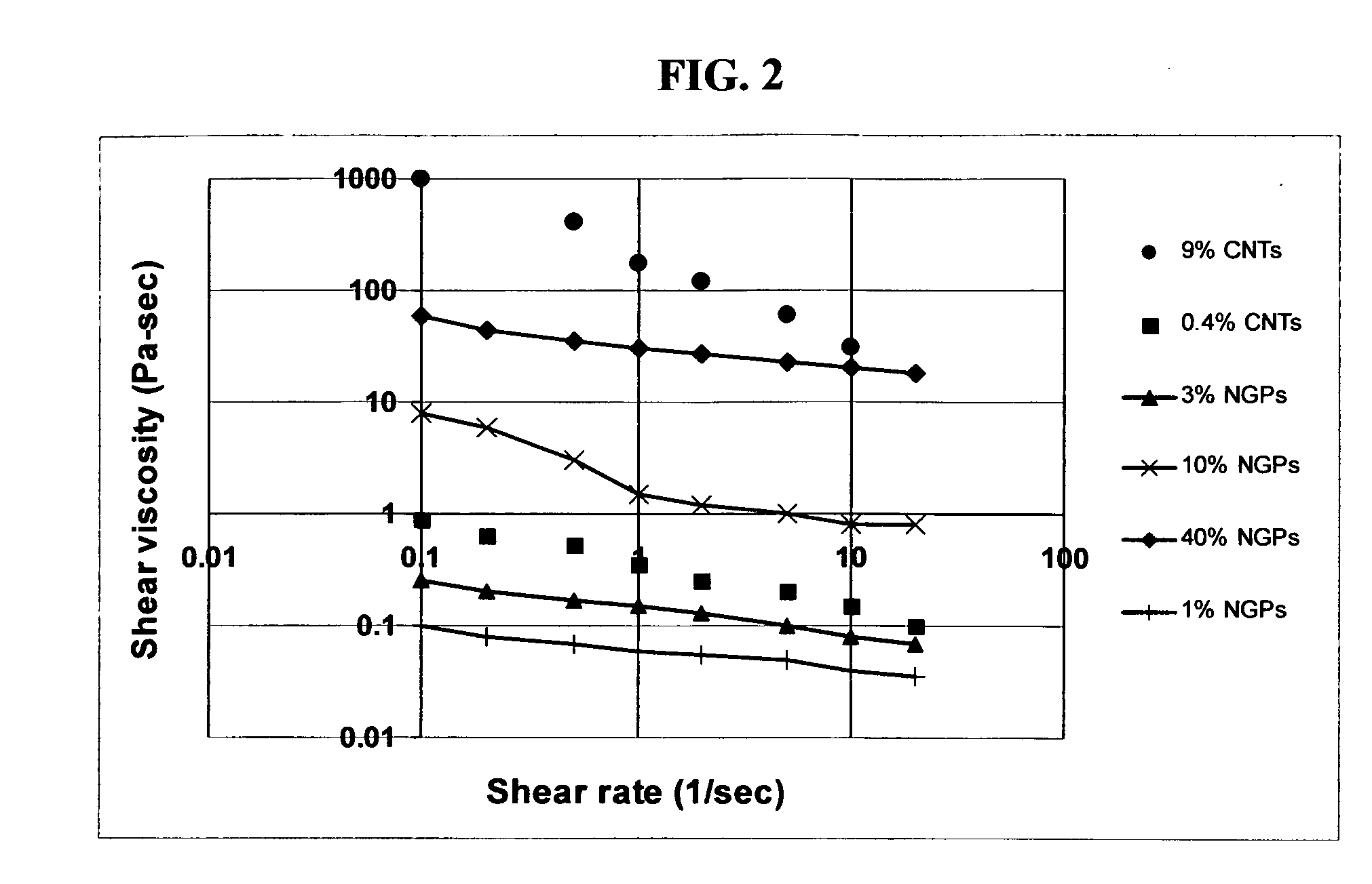
[0052]For ink viscosity studies, the NGPs used were those with an average thickness of 7.4 nm. The water content of an ink sample was adjusted by using controlled evaporation (to increase NGP volume fraction in a suspension) or adding water (to dilute it). Suspensions with a range of NGP volume fractions, up to greater than 45%, were prepared. Much thinner NGPs (1 nm) were used for electrical resistivity and thermal conductivity measurements.

Example

EXAMPLE 2
Nano-Scaled Graphene Platelets (NGPs) from Natural Graphite Flakes (No Dispersing Agent)
[0053]Five grams of graphite flakes, ground to approximately 10 μM or less in sizes, were dispersed in 1,000 mL of deionized water to obtain a suspension. An ultrasonic energy level of 95 W (Branson S450 Ultrasonicator) was used for exfoliation, separation, and size reduction for a period of 2.5 hours. The resulting NGPs, although thicker than those prepared with the assistance of a surfactant, were also well dispersed in water, forming a surfactant-free ink.

Example

EXAMPLE 3
Preparation of Inks Containing Oxidized NGPs (Graphite Oxide Platelets)
[0054]Graphite oxide was prepared by oxidation of graphite flakes with sulfuric acid, nitrate, and potassium permanganate, at a ratio of 4: 1:0.01 at 30° C., according to the method of Hummers [U.S. Pat. No. 2,798,878, Jul. 9, 1957]. Upon completion of the reaction, the mixture was poured into deionized water and filtered. The sample was then washed with 5% HCl solution to remove most of the sulfate ions and residual salt and then repeatedly rinsed with deionized water until the pH of the filtrate was approximately 7. The intent was to remove all sulfuric and nitric acid residue out of graphite interstices. The slurry was spray-dried and stored in a vacuum oven at 60° C. for 24 hours. The interlayer spacing of the resulting laminar graphite oxide was determined by the Debye-Scherrer X-ray technique to be approximately 0.73 nm (7.3 Å), indicating that graphite has been converted into graphite oxide. Graphite oxide was placed in a quartz tube, which was then inserted into a three-zone tube furnace pre-set at 1,050° C. and maintained at this temperature for 60 seconds. Nitrogen was continuously introduced into the quartz tube while graphite oxide was exfoliated. The resulting graphite oxide worms were then mixed with water and subjected to a shearing treatment using a rotating-blade device (Cowles) for 30 minutes. This procedure led to the formation of oxidized NGP dispersion or ink.

PUM

no PUM

Description & Claims & Application Information

We can also present the details of the Description, Claims and Application information to help users get a comprehensive understanding of the technical details of the patent, such as background art, summary of invention, brief description of drawings, description of embodiments, and other original content. On the other hand, users can also determine the specific scope of protection of the technology through the list of claims; as well as understand the changes in the life cycle of the technology with the presentation of the patent timeline. Login to view more.

Similar technology patents

Classification and recommendation of technical efficacy words

  • Low viscosity
  • Cost-effective

Composite materials and methods of making the same

InactiveUS20090169867A1Reduce slurry viscosityLow viscosityProtein adhesivesFibre treatmentEmulsionFormaldehyde free
Owner:ROHM & HAAS CO

Button anchor system for moving tissue

InactiveUS20060064125A1Simple and easy to useCost-effectiveSuture equipmentsSurgical veterinaryReactive componentsFull thickness
Owner:CANICA DESIGN
Why Eureka
Try Eureka