
Battery structures, self-organizing structures and related methods

a battery and self-organizing technology, applied in the field of bipolar devices, can solve the problems of high cost insufficient power density of lithium ion batteries in hybrid and electric vehicles, and insufficient power density of lithium ion batteries. achieve the effect of minimizing distance or path length and maximizing electrode interface area

Inactive Publication Date: 2010-01-07
A123 SYSTEMS LLC
View PDF86 Cites 67 Cited by
  • Summary
  • Abstract
  • Description
  • Claims
  • Application Information

AI Technical Summary

Benefits of technology

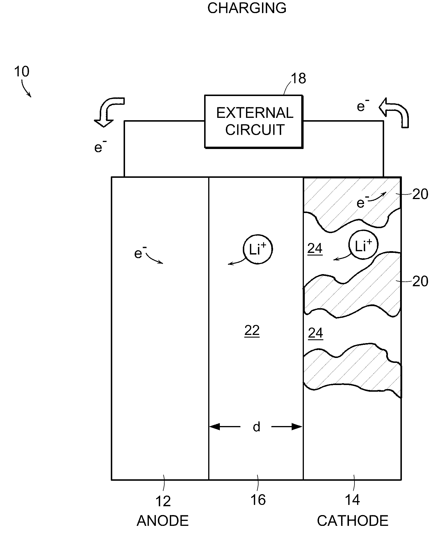
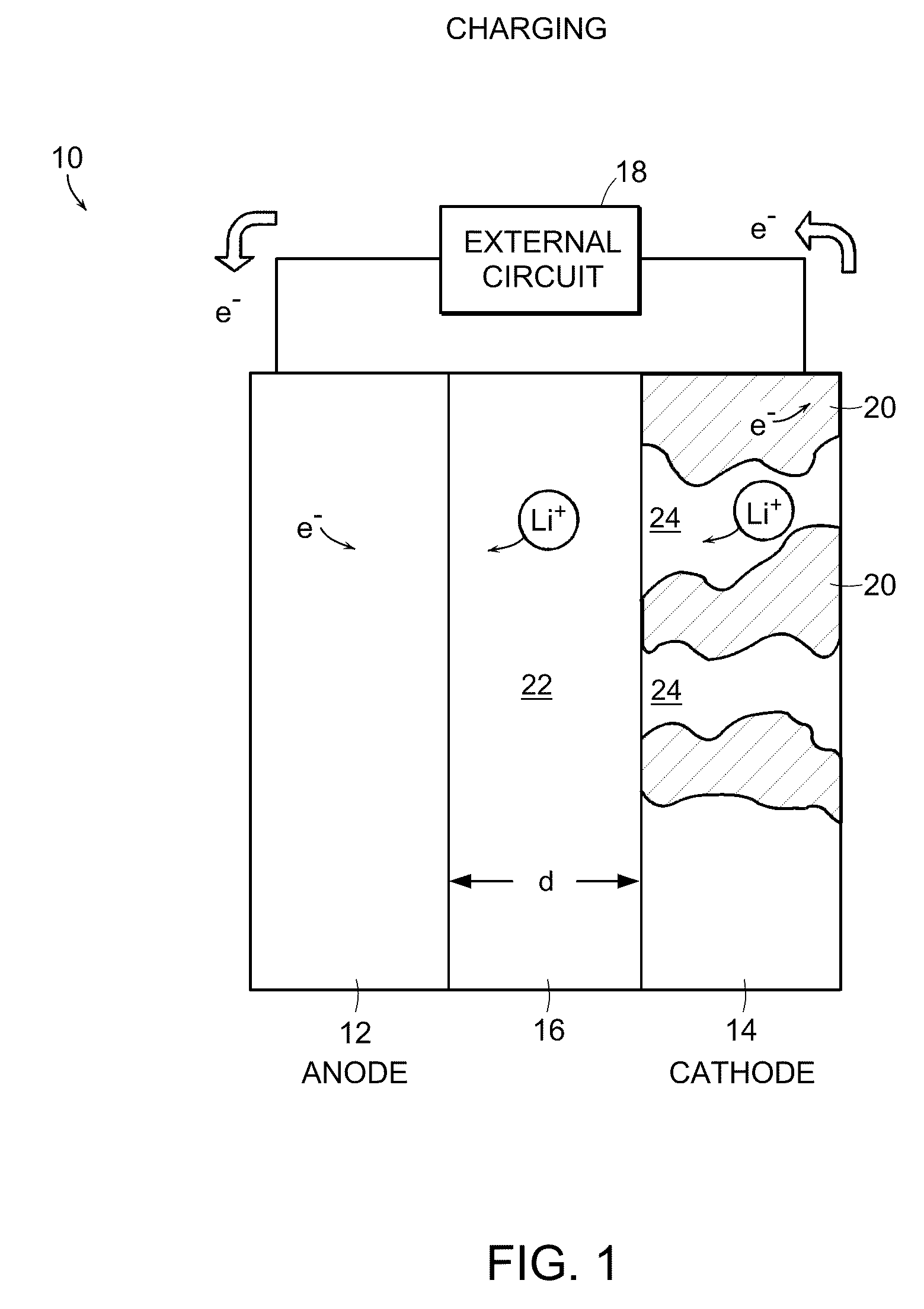
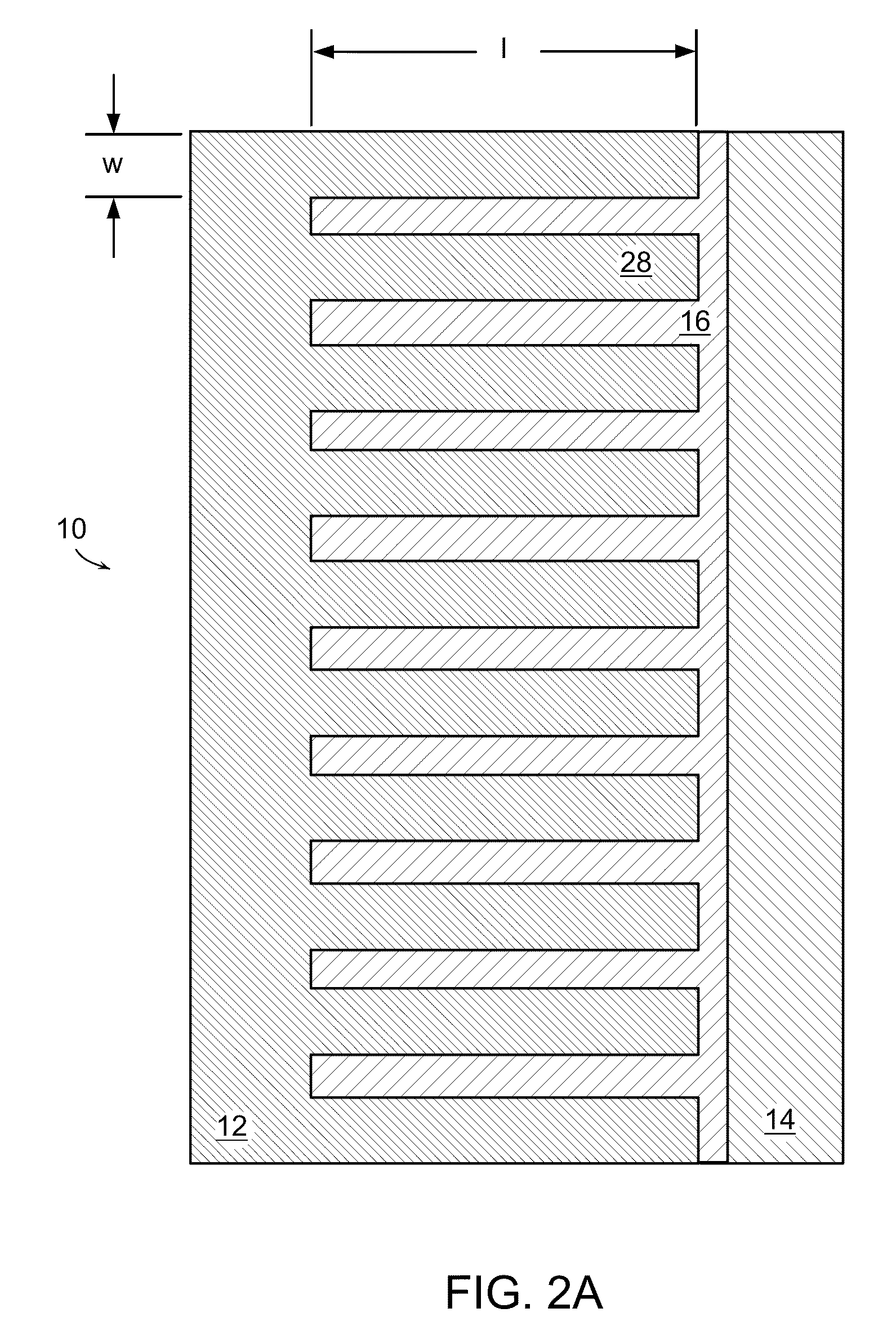
[0017]In one aspect of the invention, an electrochemical device is provided that maximizes electrode interface area with the ionically conductive medium and minimizes the distance or path length that ions and / or electrons must reliably traverse during operation of the device.
[0020]In another aspect of the invention, an electrochemical device includes first and second electrodes separated from one another by an ionically conductive medium. The device has a total thickness of greater than about 0.1 mm and the ionically conductive medium separating the first and second electrodes is no greater than 1 micron at least one location along an interface between the first and second electrodes. Thus, for the first time a bulk battery is described having inter-electrode spacings that are typical of thin film batteries. This allows higher energy densities, higher power densities, or longer cycling life to be obtained compared to conventional laminated bulk batteries known as lithium ion, lithium polymer, or lithium gel polymer batteries. For example, the length scale for power density is on the order of 1 micron for Li ion transport through electrolyte as compared to about 100 microns for conventional laminated bulk batteries. Compared to thin film batteries, batteries of much higher total energy and power, and in shapes or form factors not possible with thin film batteries, are obtained.
[0054]In another embodiment, the present invention provides a method for facilitating providing energy. The method comprises the step of providing a battery comprising a first electrode, a second electrode, a first current collector in electronic communication with the first electrode and a second current collector in electronic communication with the second electrode, wherein the first electrode includes a portion, positioned between the first current collector and the second electrode, having a porosity that increases in a direction from the first current collector toward the second electrode.

Problems solved by technology

Lithium ion batteries based on liquid electrolytes also do not enjoy the same advantage in power density that they possess in energy density.
Currently, a major limitation to the widespread use of lithium ion technology in hybrid and electric vehicles is insufficient power density and the high cost of LiCoO2.
An electrode in a lithium battery that is too thick can limit discharge rate because ion transport in and out of the electrode can be rate limiting.
Energy density then suffers because the electrolyte, separator, and current collectors occupy a higher volume and contribute to a greater mass relative to the active material of the electrodes.
Moreover, due to the need to maximize the packing density of storage material (for high energy density), the electrolyte-filled pore channels of the composite electrode are made to be tortuous and limited in cross-sectional area.

Method used


Image

  • Battery structures, self-organizing structures and related methods
  • Battery structures, self-organizing structures and related methods
  • Battery structures, self-organizing structures and related methods

Examples


example 1

Lithium Battery Prepared by Sequential Deposition

[0221]A suspension is prepared of a fine powder lithium storage cathode such as LiCoO2, LiNiO2, LiMnO2, LiMn2O4, LiFePO4, V2O5, Li3Bi, Li3Sb, or other such cathodes well-known to those skilled in the art in a solvent with a binder, optionally a conductive additive such as carbon, and other additives well-known to impart characteristics to the suspension allowing it to be deposited in thin layers using stenciling, screen printing, inkjet printing, or lithographic methods selected to allow a lateral resolution to the printed layer that is within the desired dimensional ranges. A separate suspension is similarly prepared of a fine powder lithium storage anode such as carbon, Sn, Sb, Al, Zn, Ag, LiAl or other anode materials known to those skilled in the art. The cathode suspension and anode suspension are deposited layer by layer, providing a periodic or aperiodic reticulated or interdigitated structure as described above and as shown in...

example 2

Battery Produced by Printing and Coating

[0224]A first electrode with a reticulated or interdigitated structure, either cathode or anode, is prepared using the materials and methods of Example 1. At the free surface of the printed structure, a continuous film of a binder or polymer electrolyte is formed. The film can form a physical separator between anode and cathode. The film is formed by self-segregation (wetting) of the binder solution to the free surface of the printed electrode. Optionally, the surface film is formed by coating with a liquid binder or electrolyte solution followed by drying, or by vapor deposition techniques known to those skilled in the art of thin film materials preparation.

[0225]A conformal coating of a liquid suspension is applied to the formed structure to create the counter electrode. The indentations of the latter fill in complementary fashion to the structure of the first electrode, leaving a smooth and flat outer surface to which a current collector is...

example 3

Battery Produced by Embossing and Coating

[0226]A layer of a first electrode, either cathode or anode, formulated of the materials and by the methods of Example 1, is cast or coated in a layer upon a metal foil current collector or an insulating film. This layer is formulated by methods known to those skilled in the art to have Theological characteristics appropriate for thick film processing, for example, by screen printing, tape casting, web coating, and similar processes. The surface of the first layer is then embossed with a die to leave a reticulated surface with dimensions as desired. To this shaped surface is applied a counter electrode by the conformal coating material and process described in Example 2. The assembly is dried and optionally heated for consolidation and a current collector is applied. A film of binder or electrolyte is applied before or after the embossing step, and before coating with the counter electrode formulation.


PUM

PropertyMeasurementUnit
ionic conductivityaaaaaaaaaa
thicknessaaaaaaaaaa
thicknessaaaaaaaaaa

Abstract

An energy storage device includes a first electrode comprising a first material and a second electrode comprising a second material, at least a portion of the first and second materials forming an interpenetrating network when dispersed in an electrolyte, the electrolyte, the first material and the second material are selected so that the first and second materials exert a repelling force on each other when combined. An electrochemical device, includes a first electrode in electrical communication with a first current collector; a second electrode in electrical communication with a second current collector; and an ionically conductive medium in ionic contact with said first and second electrodes, wherein at least a portion of the first and second electrodes form an interpenetrating network and wherein at least one of the first and second electrodes comprises an electrode structure providing two or more pathways to its current collector.

Description

RELATED APPLICATIONS[0001]This application is a continuation of and claims the benefit of priority under 35 U.S.C. §120 to U.S. patent application Ser. No. 10 / 206,662, entitled “Battery Structures, Self-organizing Structures and Related Methods,” which claims the benefit of priority under 35 U.S.C. § 119(e) to U.S. Provisional Patent Application No. 60 / 308,360, filed Jul. 27, 2001, and entitled “Self-Organizing Structures and Associated Methods,” the contents of all of which are incorporated by reference. Application Ser. No. 10 / 206,662 is a continuation-in-part application of U.S. patent application Ser. No. 10 / 021,740, now U.S. Pat. No. 7,533,584, originally filed Oct. 22, 2001, entitled “Reticulated and Controlled Porosity Battery Structures,” which claims priority to provisional application Ser. No. 60 / 242,124, filed Oct. 20, 2000, entitled “Microstructural Modeling of Lithium Battery Electrodes,” the contents of all of which are incorporated herein by reference.GOVERNMENT RIGHT...

Claims


Application Information

Patent Timeline
Patent Type & Authority Applications(United States)
IPC IPC(8): H01M4/58H01M4/02G02F1/1524G02F1/155H01G9/00H01G9/02H01G9/038H01G9/058H01G9/155H01M4/38H01M4/80H01M6/18H01M6/40H01M10/04H01M10/052H01M10/0525H01M10/0565H01M10/058H01M10/36
CPCG02F1/1523Y10T29/49115H01G9/038H01G9/155H01G11/02H01G11/06H01G11/24H01G11/26H01G11/56H01M4/808H01M6/18H01M6/40H01M10/0436H01M10/0472H01M10/052H01M10/0525H01M10/0565H01M10/058H01M2004/021H01M2004/025Y02E60/122Y02E60/13Y10T29/49224Y10T29/49002Y10T29/49108G02F2001/1555B33Y80/00G02F1/1524Y02E60/10Y02P70/50H01G11/28H01M4/485
Inventor CHIANG, YET-MINGMOOREHEAD, WILLIAM DOUGLASGOZDZ, ANTONI S.HOLMAN, RICHARD K.LOXLEY, ANDREWRILEY, JR., GILBERG N.VIOLA, MICHAEL S.
Owner A123 SYSTEMS LLC
Learn More