

Cryotrap and vacuum processing device with cryotrap
a vacuum processing device and cryotrap technology, which is applied in the direction of positive displacement liquid engines, separation processes, lighting and heating apparatus, etc., can solve the problems of difficult increase of operating rate, inability to achieve high exhaust speed of exhaust panel, and inability to ensure large conductance of the inside of vacuum processing apparatus, etc., to achieve rapid cooling of exhaust panel, shorten the activation time and regeneration time of cryotrap, and high exhaust capacity
- Summary
- Abstract
- Description
- Claims
- Application Information
AI Technical Summary
Benefits of technology
Problems solved by technology
Method used
Image

Examples
first embodiment
[0054]The structure and operation of a cryotrap according to the first embodiment of the present invention will be described below with reference to the accompanying drawings. The first embodiment is an example corresponding to (i) in (1) of the above-described mechanism which allows thermal connection / disconnection (connection / disconnection mechanism).
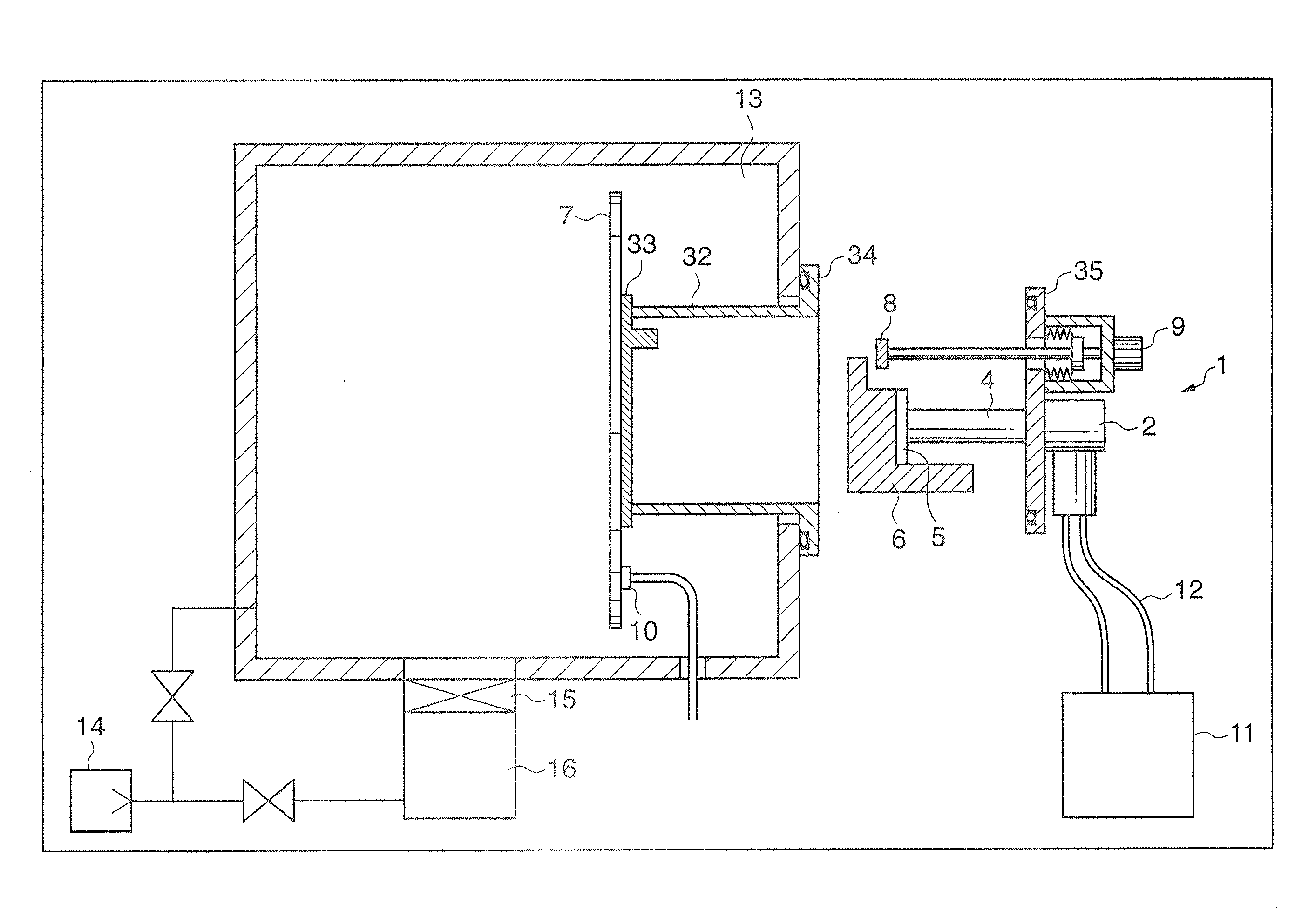
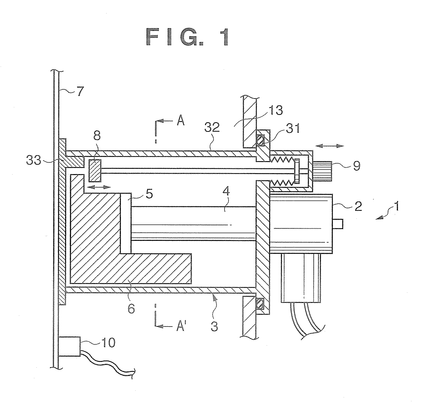
[0055]FIG. 1 is a view showing the structure of a cryotrap 1 using a G-M type refrigeration system according to this embodiment.
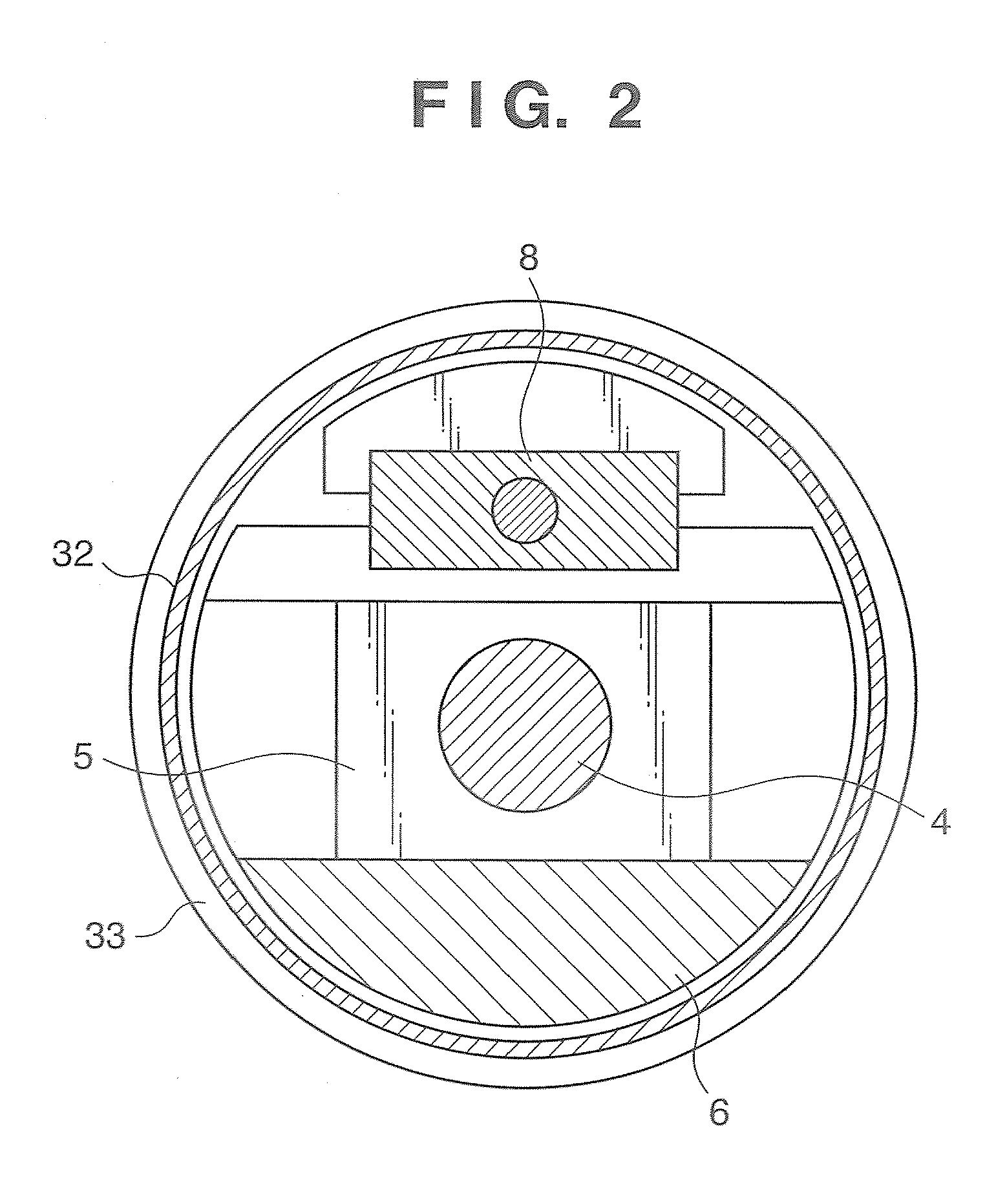
[0056]FIG. 2 is a sectional view of the cryotrap according to this embodiment taken along the line A-A′ in FIG. 1.
[0057]A vacuum vessel 3 is newly set in the cryotrap 1. The cryotrap 1 is attached to a vacuum processing apparatus 13 via the vacuum vessel 3 extending in the vacuum processing apparatus 13. In the cryotrap 1, a cooling stage 5 connected to a refrigerator 2 via a cylinder 4 is cooled by the refrigerator 2.
[0058]The G-M type refrigeration system can be substituted by another refrigeration system s...
second embodiment
[0083]The second embodiment is an example corresponding to (i) in (2) of the above-described mechanism which allows thermal connection / disconnection (connection / disconnection mechanism).
[0084]FIG. 5A is a view showing the structure of a cryotrap according to this embodiment while thermal contact between an exhaust panel and a cooling storage body is maintained.
[0085]A deformable member which has a good heat conductivity, is fixed to one of a cooling storage body 6 and an exhaust panel7, and thermally contacts and separates from the other one is inserted between the cooling storage body 6 and the exhaust panel 7. The deformable member includes a bellows 18 or the like and a contact body 17, which have good heat conductivity. The deformable member is brought into contact with both the cooling storage body 6 and the exhaust panel 7 by introducing a gas into the bellows 18 by a gas inlet pipe 19 for introducing a gas into the bellows 18 or exhausting a gas from inside the bellows 18.
[00...
third embodiment
[0091]The third embodiment is an example corresponding to (3) of the above-described mechanism which allows thermal connection / disconnection (connection / disconnection mechanism)
[0092]FIG. 6 is a view showing the structure of a cryotrap according to the third embodiment of the present invention.
[0093]In the third embodiment, neither the movable unit nor deformable member as used in the first and second embodiments are used. The cryotrap is configured to change the heat transfer characteristic between a cooling storage body 6 and an exhaust panel 7 using gaseous convection generated by introducing a gas, which has a high heat conductivity, such as helium gas into a vacant room 20 between the cooling storage body 6 and the exhaust panel 7 or exhausting a gas from inside the vacant room 20 by a gas inlet pipe 21. According to this embodiment, the cryotrap can be given a high exhaust capacity, and the exhaust panel can be cooled rapidly. This makes it possible to maintain a high operatin...
PUM
| Property | Measurement | Unit |
|---|---|---|
| Pressure | aaaaa | aaaaa |
| Electrical conductivity | aaaaa | aaaaa |
| Heat | aaaaa | aaaaa |
Abstract
Description
Claims
Application Information