
Aluminum alloy for anodizing having durability, contamination resistance and productivity, method for producing the same, aluminum alloy member having anodic oxide coating, and plasma processing apparatus

a technology of contamination resistance and productivity, applied in the direction of coatings, chemical vapor deposition coatings, metallic material coating processes, etc., can solve the problems of increased gaseous environment adopted, inability to maintain corrosion resistance and wear resistance thereof, and inability to maintain corrosion resistance and wear resistance, etc., to achieve low contamination of a member, excellent durability, and productivity. , the effect of improving the yield of the member

Inactive Publication Date: 2010-01-28
KOBE STEEL LTD
View PDF2 Cites 24 Cited by
  • Summary
  • Abstract
  • Description
  • Claims
  • Application Information

AI Technical Summary

Benefits of technology

[0022]The present invention has been made in view of these problems, and an object of the invention is to provide an aluminum alloy for anodic oxidation treatment and an aluminum alloy member having an anodic oxidation coating, or the like, which are excellent in the durability, the contamination resistance, and the productivity under a hot corrosive environment.
[0025](2) An aluminum alloy for anodic oxidation treatment that is excellent in the durability, the contamination resistance, and the productivity, wherein the aluminum alloy can be obtained by subjecting an aluminum alloy ingot which comprises as alloy elements 0.1 to 2.0 mass % Mg, 0.1 to 2.0 mass % Si, and 0.1 to 2.0 mass % Mn, and each content of Fe, Cr, Cu is limited to 0.03 mass % or less, and the remainder is composed of Al and inevitable impurities, to a homogenization treatment at a temperature of 500° C. or more to 600° C. or less.
[0033]According to the aluminum alloy and the aluminum alloy member directed to the present invention, an anodic oxidation coating excellent in the durability, the contamination resistance, and the productivity can be obtained, allowing the aluminum alloy and the aluminum alloy member to be used preferably under a hot corrosive gas environment or a plasma environment. In addition, according to the plasma processing apparatus directed to the present invention, the remarkably low contamination of a member to be treated can be realized in the plasma processing, leading to an improved yield in the production of the members to be treated.

Problems solved by technology

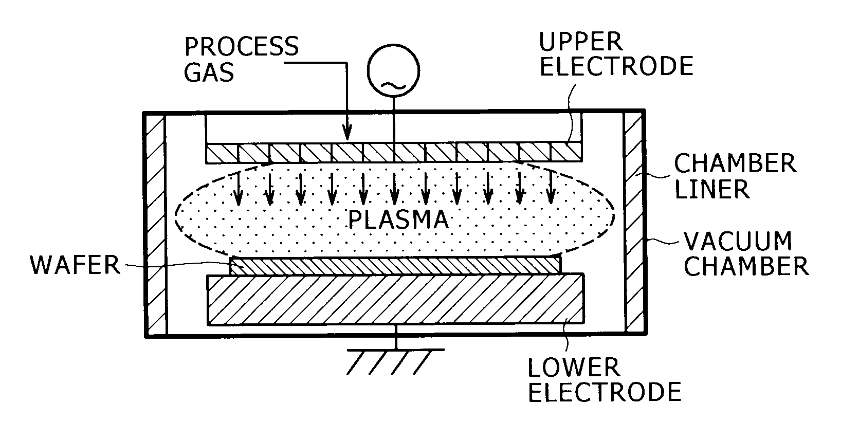
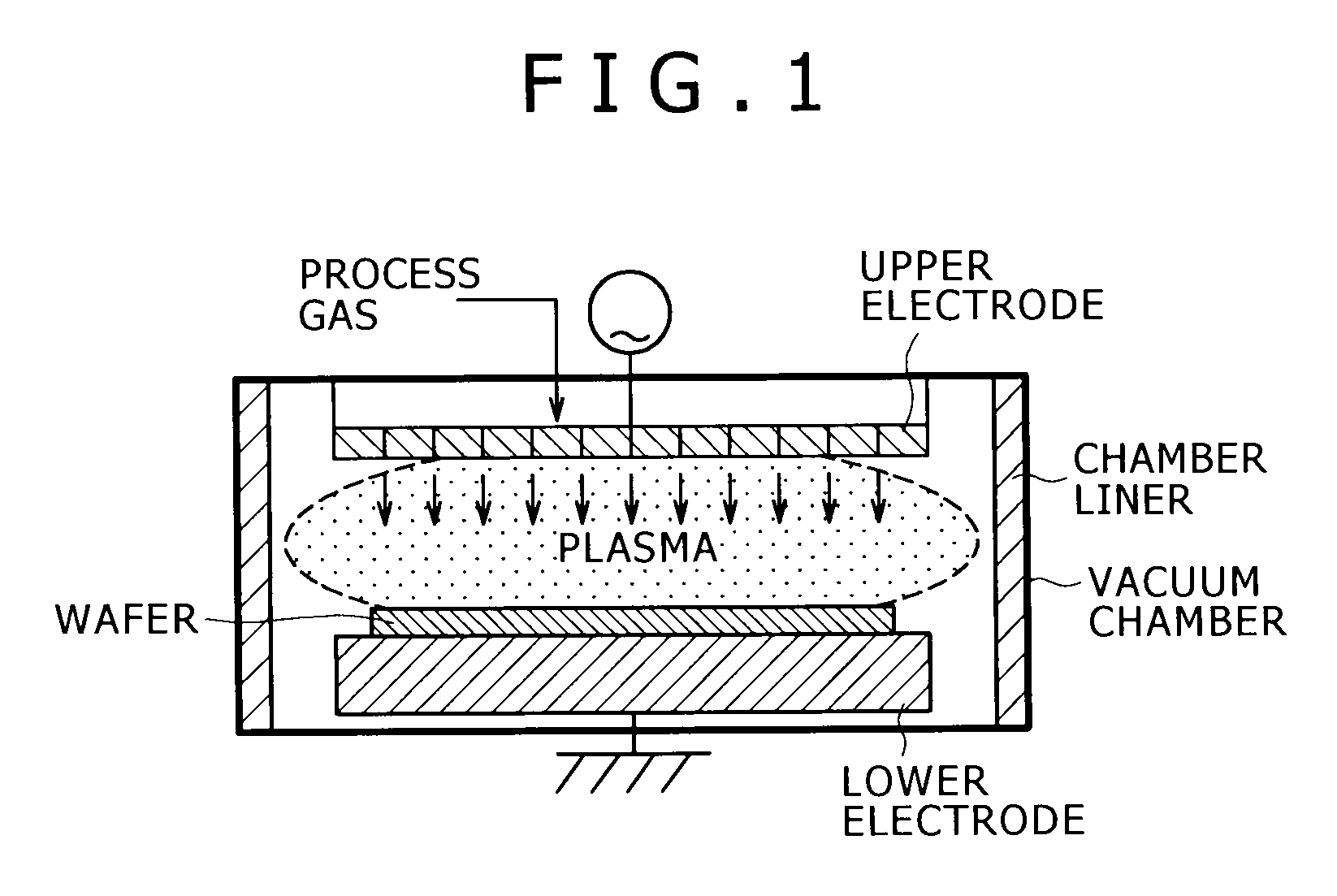
For example, a vacuum chamber used in a plasma treatment apparatus of the semiconductor production equipment and various components equipped inside the vacuum chamber, such as an electrode, are mainly formed by an aluminum alloy; however, the corrosion resistance and the wear resistance thereof cannot be maintained as far as the aluminum alloy is of a solid aluminum alloy.
That is why, inside the vacuum chamber, the certain processing is performed on a member to be treated, such as silicon wafer, by using various types of corrosive gases and plasmas under a high temperature environment ranging from room temperature to 200° C. or more, in a pretreatment process or a production process of the semiconductor production; thereby the inner face of the vacuum chamber and the various components equipped inside the vacuum chamber, such as a plasma electrode, are exposed to the environment stated above, resulting in that the corrosion resistance and the wear resistance thereof cannot be maintained as far as the aluminum alloy is of a solid aluminum alloy.
However, in recent years, the gaseous environments adopted have been more severe due to increased temperatures of the gases and the high-density growth of plasmas, as semiconductors have been highly integrated; hence, the durability of a coating (the corrosion resistance and the crack resistance under a high temperatures) has been often insufficient when an aluminum alloy that is commercially available as stated above, is used as a substrate.
In addition, even when the durability of a coating is sufficient, there have been problems in that, because elements that have been added into the aluminum alloy substrate and impurity elements are contained in the coating, and because these elements are emitted in the gas from the coating, members to be treated are contaminated.
However, because Cu and Fe, which could be contamination sources, are contained in the above aluminum alloy substrates, a sufficient effect cannot be expected for reducing the contamination of members to be treated, and there is also a problem in that the durability of the coating is insufficient under current gaseous environments adopted.
In addition, there has been a problem in that the growth rate of an anodic oxidation coating is very slow on the aluminum alloys, resulting in the poor productivity.

Method used


Image

  • Aluminum alloy for anodizing having durability, contamination resistance and productivity, method for producing the same, aluminum alloy member having anodic oxide coating, and plasma processing apparatus
  • Aluminum alloy for anodizing having durability, contamination resistance and productivity, method for producing the same, aluminum alloy member having anodic oxide coating, and plasma processing apparatus
  • Aluminum alloy for anodizing having durability, contamination resistance and productivity, method for producing the same, aluminum alloy member having anodic oxide coating, and plasma processing apparatus

Examples


example 1

Evaluation Test Method

[0052]The following evaluation tests were carried out to establish the effects of the present invention. An aluminum alloy ingot having the element composition shown in the following Table 1 was produced (size: 220 mm W×250 mm L×100 mm t, cooling rate: 10 to 15° C. / s). After cutting and facing the ingot (size: 220 mm W×150 mm L×60 mm t), the material was subjected to a homogenization treatment (540° C.×4 h); subsequently, the material having a thickness of 60 mm was subjected to the hot-rolling to be formed into a sheet material having a thickness of 6 mm. After being subjected to a solution treatment (510 to 520° C.×30 min), the sheet material was subjected to a water quenching and an aging treatment (160 to 180° C.×8 h) to obtain an alloy sheet for the test. Test specimens having a size of 25 mm×35 mm (hot-rolling direction)×3 mm t, were cut out from the alloy sheet, of which surface was subsequently subjected to a facing process so as to have a surface rough...

example 2

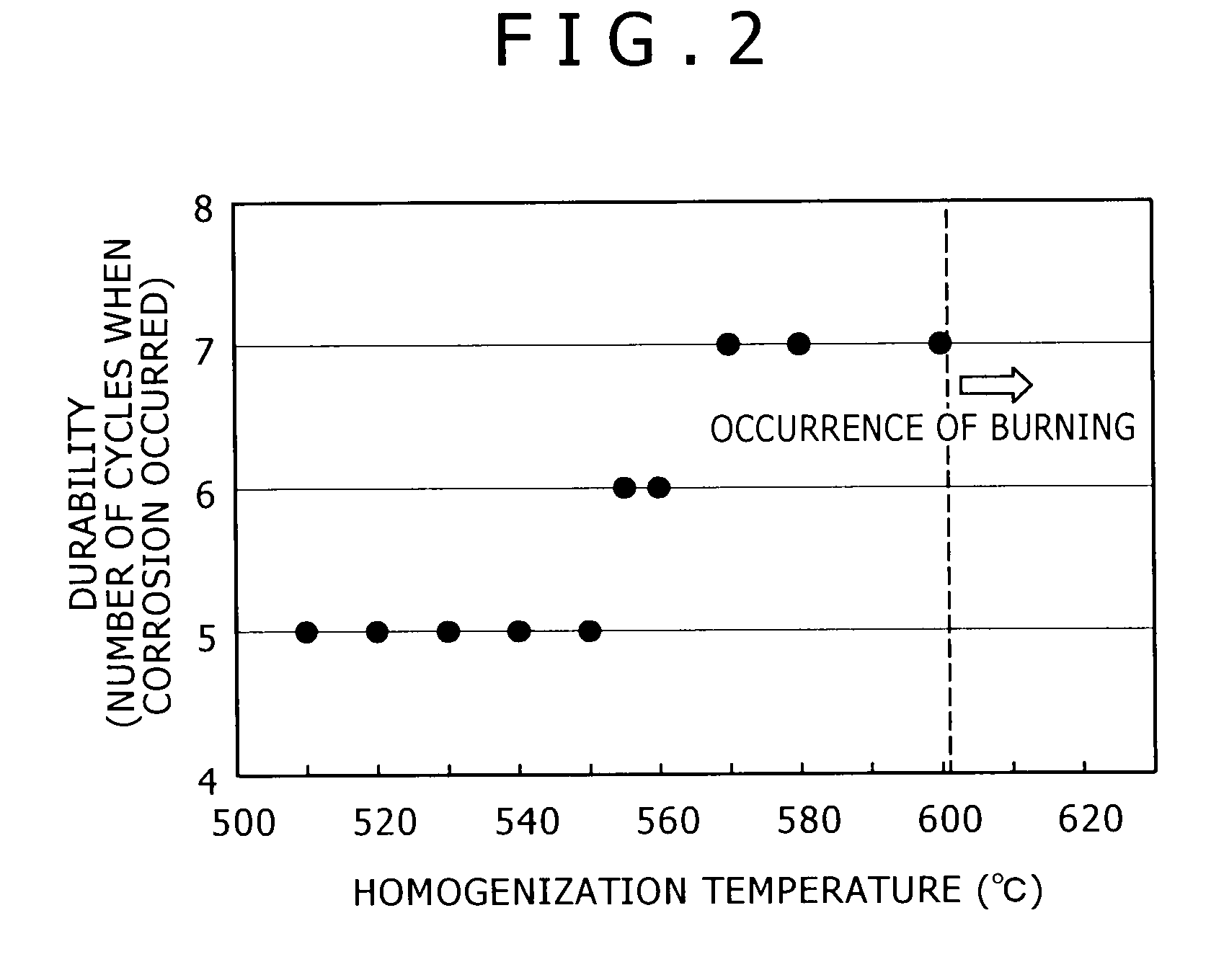
[0062]In the above Example 1, the effect by the element composition of the aluminum alloy ingot was investigated with a homogenization temperature being constant (540° C.), and with the element composition of the aluminum alloy ingot being changed to various modes. In the present Example, the effect of a homogenization temperature on each property of the aluminum alloy, such as the durability, was investigated with the element composition of the aluminum alloy being fixed to a constant value within the content-ranges specified by the present invention, and with a homogenization temperatures being changed. That is, a homogenization temperature was sequentially changed within a range of 510 to 605° C., while the element composition of the aluminum alloy was fixed to that listed in the following Table 2 (equivalent to No. 13 in Example 1). Other than that, the evaluation tests were carried out on the same conditions as those of Example 1.

TABLE 2Element Composition (Mass)MgSiMnFeCrCu1.0...


PUM

PropertyMeasurementUnit
Temperatureaaaaaaaaaa

Abstract

The aluminum alloy for anodic oxidation treatment directed to the present invention comprises as alloy elements 0.1 to 2.0% Mg, 0.1 to 2.0% Si, and 0.1 to 2.0% Mn, wherein each content of Fe, Cr, and Cu is limited to 0.03 mass % or less, and wherein the remainder is composed of Al and inevitable impurities. An aluminum alloy more excellent in the durability can be obtained by subjecting the aluminum alloy ingot having the above element composition to a homogenization treatment at a temperature of more than 550° C. to 600° C. or less. An aluminum alloy member can be obtained by forming an anodic oxidation coating on the surface of the aluminum alloy.

Description

TECHNICAL FIELD[0001]The present invention relates to: an aluminum alloy suitable for an anodic oxidation treatment, which is preferably utilized as a material for a vacuum chamber used in a plasma processing apparatus, such as the production equipment for semiconductors and liquid crystals, and for components equipped inside the vacuum chamber; a method for producing the aluminum alloy; and an aluminum alloy member in which an anodic oxidation coating is formed on the surface of the aluminum alloy.BACKGROUND ART[0002]Conventionally, anodic oxidation treatments have been frequently used, in which an anodic oxidation coating is formed on the surface of an aluminum alloy, a substrate, such that the corrosion resistance (the corrosion resistance to hot gases) and the wear resistance or the like are provided to the substrate. For example, a vacuum chamber used in a plasma treatment apparatus of the semiconductor production equipment and various components equipped inside the vacuum cham...

Claims


Application Information

Patent Timeline
IPC IPC(8): C22F1/04C22C21/02C22C21/08C22F1/043C22F1/047C23C16/40
CPCC22C21/00C22C21/02C25D11/04C22F1/043C22F1/047C22C21/08C22F1/04
Inventor WADA, KOJIHISAMOTO, JUNTANAKA, TOSHIYUKIHOSHINO, KOZOKOBAYASHI, KAZUNORI
Owner KOBE STEEL LTD
Learn More