Skin preparation device and biopotential sensor

a preparation device and sensor technology, applied in the field of skin preparation devices, can solve the problems of long flexile tines that lack uniform orientation and insertion angle into the skin, limiting the ability unwanted noise in the signal, so as to reduce the overall area of skin affected, reduce the impedance, and the effect of high quality

Active Publication Date: 2010-01-28
TYCO HEALTHCARE GRP LP
View PDF12 Cites 66 Cited by
  • Summary
  • Abstract
  • Description
  • Claims
  • Application Information

AI Technical Summary

Benefits of technology

[0015]The device of the present invention includes an array of rigid tines. The tines serve to “self-prepare” the skin at each electrode site, providing for sufficiently low impedances required to collect high quality electrophysiological signals. These structures, when pressed against the skin (i.e. “prepping the skin”), penetrate the stratum corneum, thereby reducing skin impedance and improving signal quality. The function of this invention is to acquire repeatable bioelectrical signals with impedance less than 20 kΩ per electrode. These bioelectrical signals can then be transmitted from the electrode surface via the sensor conductors (leads) to the monitoring system. A self-prepping device of the present invention is an optimized array of short non-conductive rigid tines in which the individual tines are created in a geometry that allows for a sharp point at the tip when molding, machining or etching is used as a method of fabrication. This non-conductive array with rigid penetrating structures may, therefore, be used in combination with a conductive medium, preferably an ionic conductive gel. In penetrating the stratum corneum, micro-conduits are created in the layers of the skin enabling the conductive medium to reach the low impedance layers and to transmit bioelectrical signals from the skin to the electrode surface. Such a self-prepping device can be readily mass produced using molding methods or possibly other manufacturing methods, thereby providing for a low cost means of achieving improved performance of the biopotential sensor. Additionally this invention includes the integration of this self-prepping device into a biopotential sensor comprising an array of one or more electrodes.

Problems solved by technology

Additionally, variance in impedance between electrode sites can result in unwanted noise in the signal.
Long flexile tines lack uniformity of orientation and insertion angle into the skin.
Due to their size, macro-sized tines, as described in U.S. Pat. No. 5,305,746, limit the potential density of the tines in the array thereby also limiting the ability to reduce the overall electrode size and overall area of skin that is affected while maintaining equivalent signal quality.
In addition, long tines facilitate being pressed too deeply into the skin causing unnecessary penetration beyond the stratum corneum while a shorter tine limits the deformation of the skin.
The complexity of this design does not support the cost effectiveness and ease of manufacturing required for a disposable electrode and skin preparation device.
These needles for transdermal drug delivery have no conductive requirement because they do not serve to transmit any electrical signal away from the skin.
These factors result in a non-cost effective design for molding, particularly for a disposable device.
This approach is a highly effective means of creating very small, conductive tines in an array, however the cost and time associated with the growth of these arrays is currently prohibitive for integration into a high volume disposable product.
The same drawbacks apply to microneedles formed using dry-etching of silicon, as it is a multi-step manufacturing process with high development costs.

Method used


Image

  • Skin preparation device and biopotential sensor
  • Skin preparation device and biopotential sensor
  • Skin preparation device and biopotential sensor

Examples


Embodiment Construction

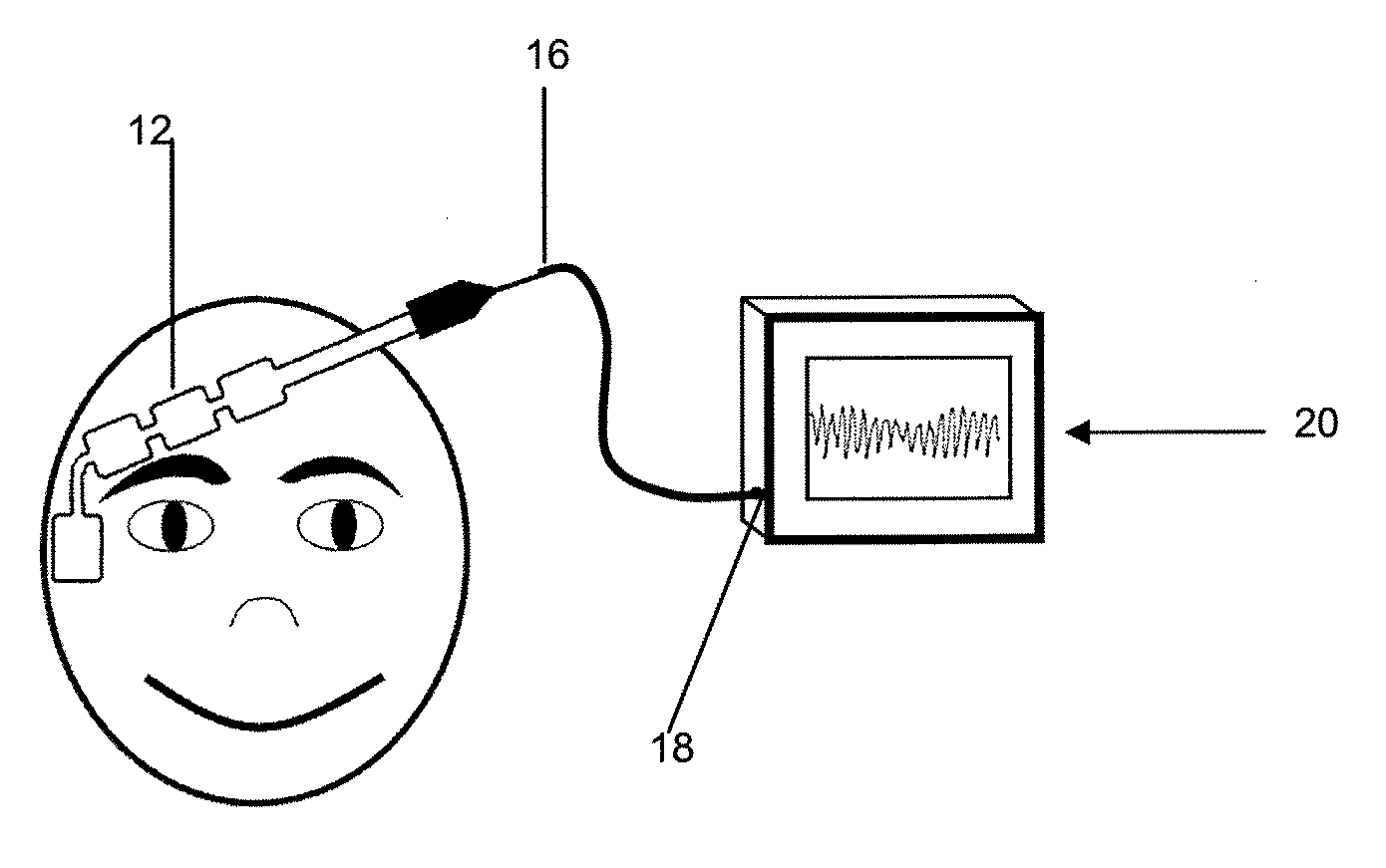
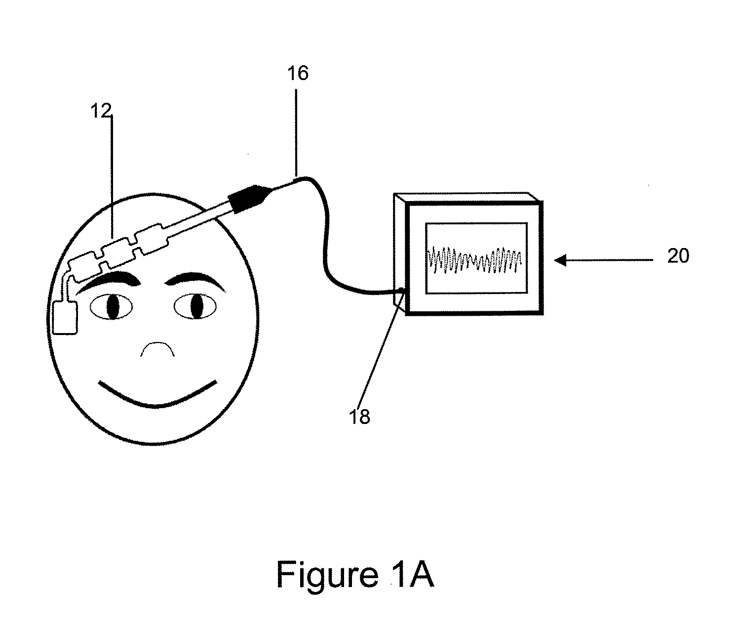
[0035]A biopotential sensor 12 shown in FIGS. 1A and 1B is a device that contains an array of one or more electrodes 14 and a set of conductors that provide an electrical conduction path for the acquired signals from the electrodes 14 to a single terminating connector 16 which in turn connects to the mating receptacle 18 of the biopotential monitoring system 20. The sensor device 12 may be coupled to the monitoring system via a terminating connector 16 inserted into a mating receptacle 18 on the monitoring system 20. Once electrical connection is achieved, the monitoring system 20 may perform analysis of the acquired biopotential signals.

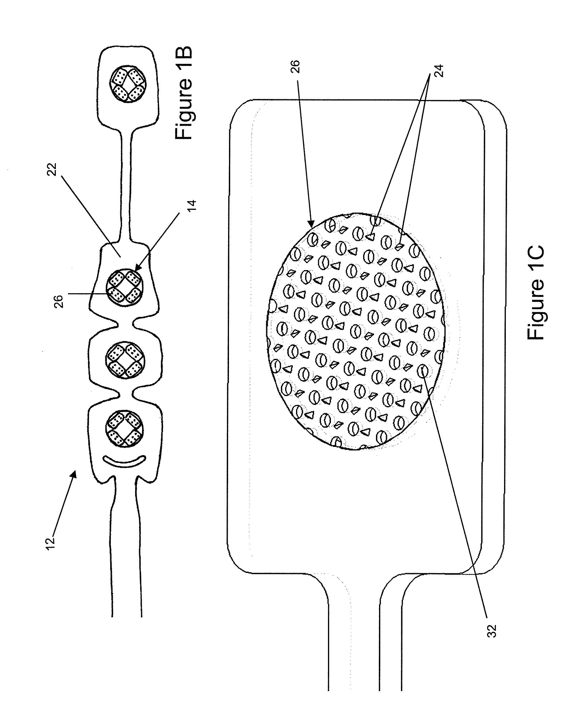
[0036]The biopotential sensor 12 includes one or more electrodes 14. In the embodiment of the biopotential sensor 12 shown in FIG. 11B, the sensor 12 is comprised of four electrodes 14. In this embodiment, the sensor 12 includes a flexible substrate 22 with an adhesive layer on at least portions of the substrate 22 to enable secure placement on the ...


PUM


Abstract

The skin preparation device and sensor of the present invention include an array of rigid tines. The tines serve to “self-prepare” the skin at each electrode site. These tines, when pressed against the skin, penetrate the stratum corneum, thereby reducing skin impedance and improving signal quality. A self-prepping device of the present invention is an optimized array of short non-conductive rigid tines in which the individual tines are created in a geometry that allows for a sharp point at the tip when molding, machining or etching is used as a method of fabrication. This non-conductive array with rigid penetrating structures may, therefore, be used in combination with a conductive medium, preferably an ionic conductive gel. In penetrating the stratum corneum, micro-conduits are created in the layers of the skin enabling the conductive medium to reach the low impedance layers and to transmit bioelectrical signals from the skin to the electrode surface. Such a self-prepping device can be readily mass produced using molding methods or possibly other manufacturing methods, thereby providing for a low cost means of achieving improved performance of the biopotential sensor. Additionally this invention includes the integration of this self-prepping device into a biopotential sensor comprising an array of one or more electrodes.

Description

CROSS REFERENCE TO RELATED APPLICATION[0001]This application claims benefit of Provisional Application Ser. No. 61 / 126,849, filed on May 2, 2008.BACKGROUND OF THE INVENTION[0002]This invention relates to a skin preparation device that can be used to penetrate the outermost layer of skin to allow for the penetration and / or displacement of the stratum corneum. A typical use of such invention is in the non-invasive monitoring of electrophysiological signals. This skin preparation device may be integrated into the electrodes of a biopotential sensor.[0003]The human skin tissue is composed primarily of connective tissue, the dermis, covered by a protective layer, the epidermis. The outermost layer of the epidermis is the stratum corneum. In the study of electrophysiological monitoring using surface electrodes, the stratum corneum is significant, due to its function as a protective barrier. The stratum corneum is on average approximately 20 μm thick, and is composed primarily of denucleat...

Claims


Application Information

Patent Timeline
Patent Type & Authority Applications(United States)
IPC IPC(8): A61B5/04
CPCA61B5/0478A61B5/6841A61B2562/125A61M2037/0046A61M37/0015A61M2037/0038A61B17/205A61B5/291
Inventor CORDERO, RAFAEL M.HARHEN, ROBERTKINNEY, MELISSAHOUTCHENS, GRAHAMDAVIDSON, MARCBRUMER, REBECCA
Owner TYCO HEALTHCARE GRP LP
Why Eureka
Try Eureka