Device and method for cooling hot strip

a technology of hot strip and device, which is applied in the direction of heat treatment equipment, lighting and heating equipment, furniture, etc., can solve the problems of reducing yield, affecting the cooling effect, so as to reduce the yield loss, stabilize the cooling effect, suppress the effect of material unevenness

Active Publication Date: 2010-02-04
JFE STEEL CORP
View PDF1 Cites 16 Cited by
  • Summary
  • Abstract
  • Description
  • Claims
  • Application Information

AI Technical Summary

Benefits of technology

[0015]The present invention allows the hot strip to be uniformly and stably cooled at the high cooli

Problems solved by technology

However, the structure has not satisfied the requirements yet in view of practical use.
When cooling the steel plate with the warped leading end or the warped trailing end, the steel plate may impinge against the slit nozzle unit to be damaged, and the steel plate cannot be moved; thus causing interruption of the manufacturing line and reducing the yielding.
In such a case, the leading end or the trailing end cannot be sufficiently cooled, thus failing to obtain the intended material.
Additionally the lift mechanism may increase the facility cost.
When the nozzle is brought to be

Method used


Image

  • Device and method for cooling hot strip
  • Device and method for cooling hot strip
  • Device and method for cooling hot strip

Examples


embodiments

Embodiment 1

[0136]In Embodiment 1, the cooling device 51 according to the present invention is disposed at the output side of the finishing stand 62 as shown in FIGS. 18, 19 and 20 for manufacturing the hot strip. In the manufacturing conditions, the slab with the thickness of 240 mm is heated to 1200° C. in the heating furnace 60, rolled by the roughing stand 61 to the thickness of 35 mm, and further rolled by the finishing stand 62 at the temperature at the end of finishing of 850° C. to the thickness of 3.2 mm. It is then cooled by the cooling device to 450° C. so as to be coiled by the coiler 63.

[0137]In Examples 1 to 5, the cooling device 51 according to the present invention (cooling device 20 according to the first aspect, cooling device 40 according to the second aspect) is disposed as shown in FIGS. 18 and 19 to cool the finished strip. In Comparative Examples 1 to 3 as shown in FIG. 20, the finished strip is cooled by the existing cooling device 52 without using the coolin...

example 1

[0138]In Example 1, the cooling device 51 of the present invention was disposed at the output side of the finishing stand 62 as shown in FIG. 18 for cooling the strip finished at 850° C. to 450° C.

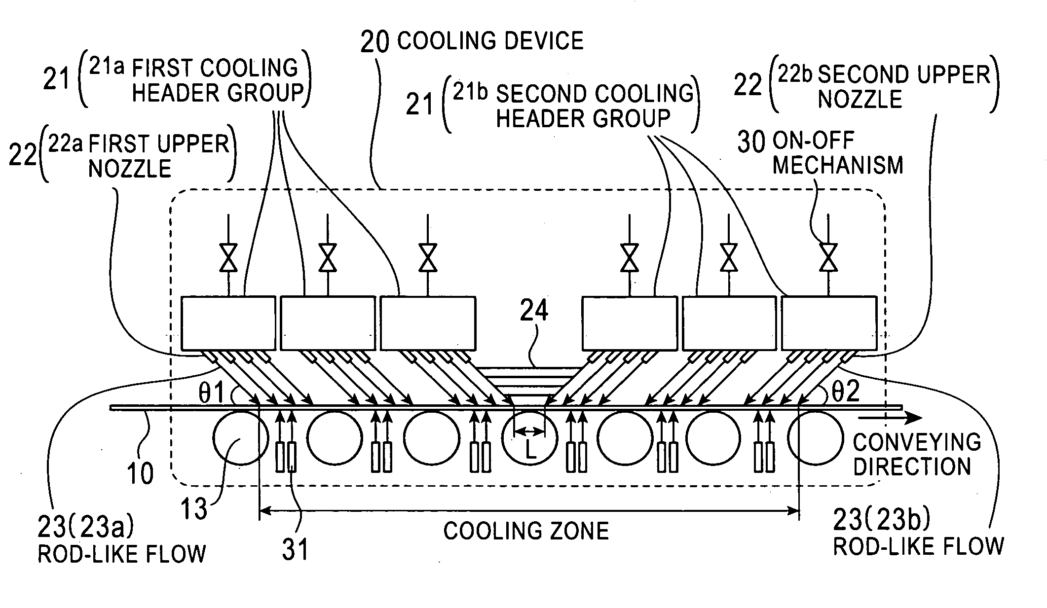
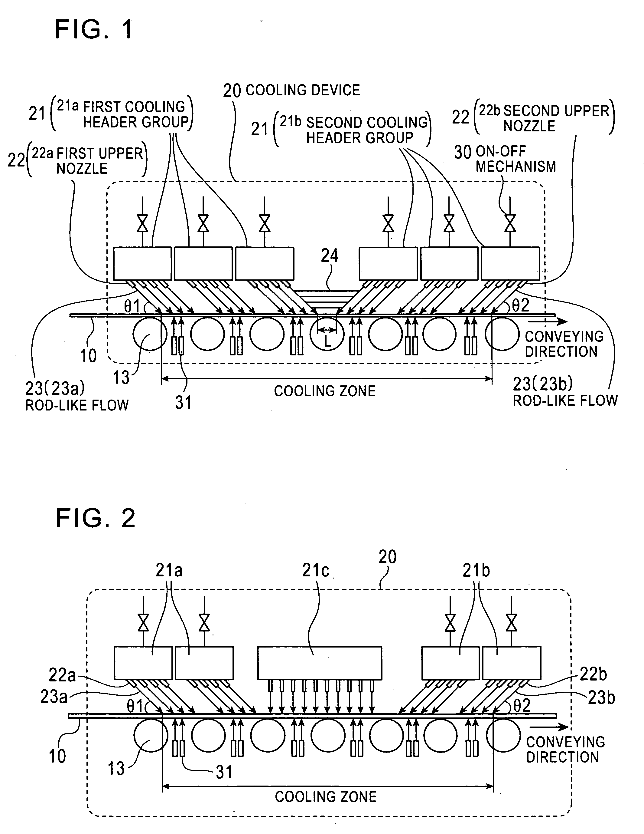
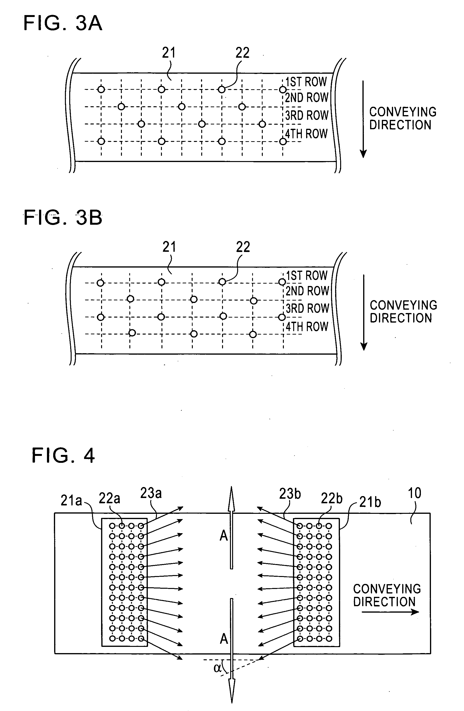
[0139]In this case, the cooling device 20 according to the first aspect was used as the cooling device 51 of the present invention, using 10 upper headers 21a and 21b (20 upper headers in total) each at the depression θ of 45° in the conveying direction, and 20 spray cooling headers corresponding to the upper headers for cooling the lower side. As the nozzles for the upper headers 21, round type nozzles 22 (inner diameter: 8 mm) were inclined outward in the width direction at the installation pitch of 70 mm in the width direction at the same outward angle (α=20°). The round type nozzles 22 in four rows were installed in the upper headers 21 in the strip conveying direction, and the injection rate of the rod-like flow was set to 8 m / s. The upper nozzle 22 was positioned at the height 1200 m...

example 2

[0141]In Example 2, the cooling device 51 of the present invention was disposed at the output side of the finishing stand 62 as shown in FIG. 18 for cooling the strip finished at 850° C. to 450° C.

[0142]Example 2 was substantially the same as Example 1 except that the number of the headers for injecting the coolant was changed for correcting the difference between the temperature measured by the thermometer 65 disposed at the output side of the cooling device 51 while cooling the strip and the target temperature.


PUM

PropertyMeasurementUnit
Fractionaaaaaaaaaa
Angleaaaaaaaaaa
Angleaaaaaaaaaa

Abstract

A cooling device and a cooling method for a hot strip allow uniform and stable cooling of the strip at a high cooling rate when supplying the coolant to the upper surface of the hot strip. The cooling device includes an upper header unit 21 for supplying a rod-like flow to the upper surface of the strip 10. The upper header unit 21 is formed of the first upper header group including plural first upper headers 21a arranged in a conveying direction and a second upper header group including plural second upper headers 21b arranged in the conveying direction. The cooling device is provided with an ON-OFF mechanism 30 to allow each of the upper headers 21a and 21b of the first and the second upper header groups to independently execute the ON-OFF control (start/end injection control) of an injection (feeding) of the rod-like flow.

Description

TECHNICAL FIELD[0001]The present invention relates to a device and a method for cooling a hot strip in a hot rolling line.BACKGROUND ART[0002]In general, the hot strip is produced by rolling a slab heated at a high temperature into a desired size, and is cooled with coolant in the hot rolling process or on the run out table after the finish rolling. The above-described cooling with the coolant is performed for the purpose of adjusting the material to obtain the intended strength and ductility by mainly controlling the deposition and transformation of the strip. The accurate control of the temperature at the end of cooling is especially essential to produce the hot strip which exhibits the intended material properties with no variation.[0003]Meanwhile, the generally employed cooling facility (water cooling facility) for the cooling with the coolant may cause such problems as the temperature unevenness or failure to control the intended temperature at the end of cooling.[0004]The afor...

Claims


Application Information

Patent Timeline
IPC IPC(8): B21B37/74C21D1/667C21D9/573
CPCB21B45/0218B21B45/0233F27D15/0206C21D9/46C21D1/667B21B45/02
Inventor UEOKA, SATOSHINAKATA, NAOKIKUROKI, TAKASHINISHIURA, NOBUO
Owner JFE STEEL CORP
Why Eureka
Try Eureka