
Optical recording medium, optical recording apparatus, and system to prepare contents-recorded optical recording medium

a recording medium and optical recording technology, applied in the field of optical recording mediums, can solve the problems of noise components that are hardly removable by frequency filtering, insufficient recording sensitivity or light absorption, and low-to-low-type dvds, etc., and achieve excellent recording sensitivity

Inactive Publication Date: 2010-02-04
RICOH KK
View PDF4 Cites 2 Cited by
  • Summary
  • Abstract
  • Description
  • Claims
  • Application Information

AI Technical Summary

Benefits of technology

[0012]It is an object of the present invention to provide an optical recording medium of low-to-high type where reflectance is high after recording compared to before recording at recording mark portions, in which the optical recording medium has a dye recording layer capable of recording by use of recording light having a wavelength of 640 to 680 nm or 400 to 410 nm and exhibits excellent recording sensitivity, and also an optical recording apparatus, and a system to prepare a contents-recorded optical recording medium by use of the optical recording apparatus.

Problems solved by technology

Recordable DVD capable of high-speed recording has been demanded recently along with enlarging capacity of optical recording media, however, the conventional DVD of high-to-low type suffers from insufficient recording sensitivity or light absorptance and / or insufficient recording properties at high-speed recording since reflectance at recording mark portions before recording is larger than that of after recording.
In this case, signals due to guide grooves are likely to mix in data signals as a noise component, in particular, when signal noises generate from the guide grooves with a frequency similar to that of data signals, there arises a problem that noise components are hardly removable by use of frequency filters.
Then commonly used reproducing apparatuses are produced on the basis of conventional optical recording media of high-to-low type (intermixed with higher reflectance access regions), thus it is likely to arise problems of servo failure etc. in the optical recording media of low-to-high type in which lower reflectance access regions being intermixed.

Method used


Image

  • Optical recording medium, optical recording apparatus, and system to prepare contents-recorded optical recording medium
  • Optical recording medium, optical recording apparatus, and system to prepare contents-recorded optical recording medium
  • Optical recording medium, optical recording apparatus, and system to prepare contents-recorded optical recording medium

Examples


example 1

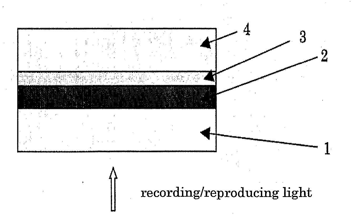
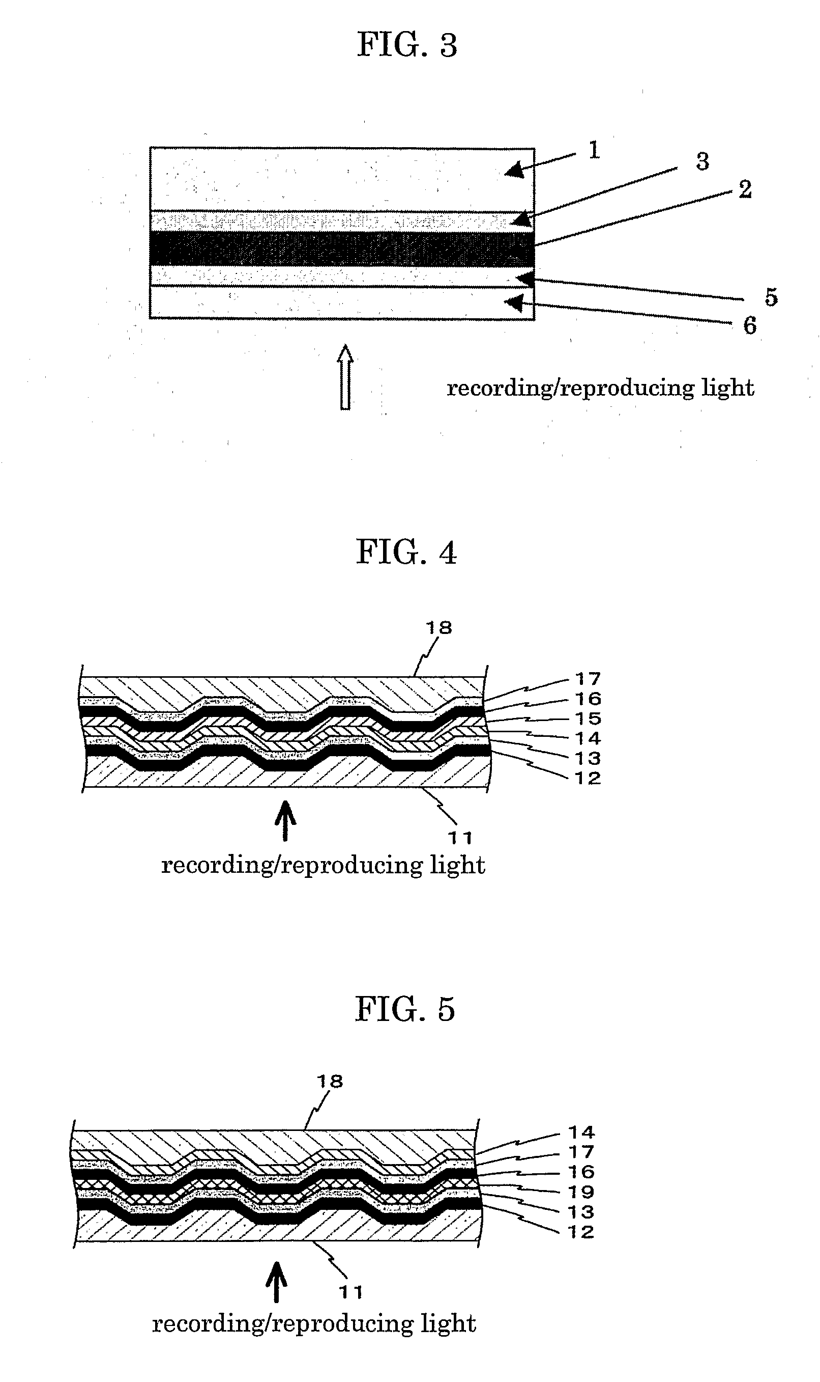
[0237]A substrate 1 of a polycarbonate disc of 120 mm diameter and 0.6 mm thick was obtained that had a concavo-convex pattern of guide grooves with about 700 Å deep, about 0.24 μm of groove bottom width, and 0.74 μm of track pitch in accordance with DVD+R format.

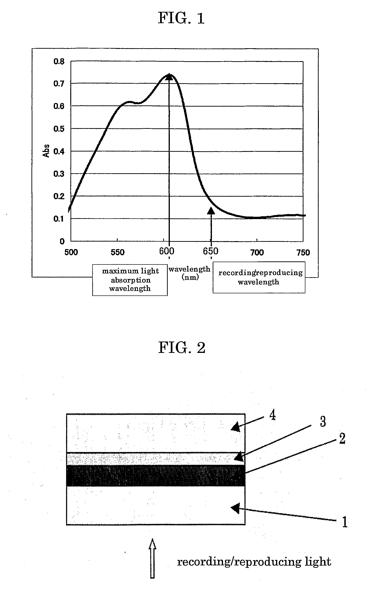
[0238]Then the cyanine dye No. 12 shown below was dissolved in 2,2,3,3-tetrafluoropropanol to prepare a coating liquid for dye recording layer, which was then spin-coated on the substrate 1 and annealed at 90° C. for 15 minutes thereby to form a dye recording layer 2. The maximum light absorption wavelength of the dye recording layer 2 was 730 nm, the light absorption (Abs.) was 0.55 at the maximum light absorption wavelength, and the light absorption (Abs.) was 0.49 at the recording / reproducing wavelength 650 nm. Separately, the dye recording layer was formed on a glass plate, and the light absorption spectrum thereof is shown in FIG. 7.

No. 12 (in the chemical formula below, Me represents a methyl group and Bu represents a...

example 2

[0246]An optical recording medium of DVD+R was produced and evaluated in the same manner as Example 1 except that the dye in the dye recording layer 2 was changed into the squarylium dye No. 13 shown below. The results are shown in Table 2. Separately, the dye recording layer was formed on a glass plate, and the light absorption spectrum thereof is shown in FIG. 7.

No. 13

[0247]

example 3

[0248]An optical recording medium of DVD+R was produced and evaluated in the same manner as Example 1 except that the dye in the dye recording layer 2 was changed into the phthalocyanine dye No. 14 shown below and 2,2,3,3-tetrafluoropropanol was changed into a mixture of 2,2,3,3-tetrafluoropropanol, ethylcyclohexane, and 1-methoxy-2-butanol. The results are shown in Table 2. Separately, the dye recording layer was formed on a glass plate, and the light absorption spectrum thereof is shown in FIG. 7.

No. 14 (in the chemical formula, R1 and R3 each represent CF3, R2 represents a phenyl group, and M represents VO (vanadium oxide))


PUM

PropertyMeasurementUnit
wavelengthaaaaaaaaaa

Abstract

An optical recording medium, comprising a dye recording layer, wherein a recording mark portion is formed at the dye recording layer by use of a laser light having a wavelength of 640 nm to 680 nm, and a reflectance after recording with respect to the laser light at the recording mark portion is increased compared to a reflectance before recording.

Description

TECHNICAL FIELD[0001]The present invention relates to an optical recording medium, of so-called low-to-high type, that has a dye recording layer capable of recording with DVD laser wavelengths of 640 to 680 nm or blue laser wavelengths of 400 to 410 nm, in which reflectance at recording portions increases or rises upon recording compared to that before recording, and also to an optical recording apparatus and a system to prepare a contents-recorded optical recording medium.BACKGROUND ART[0002]In addition to optical recording media such as reproduction-only (read-only) DVD (digital versatile disc), recordable DVD such as DVD+RW, DVD+R, DVD-R, DVD-RW and DVD-RAM have been commercially available. These DVD are extended from conventional CD-R and CD-RW (recordable compact disc) in a technical sense and designed to conform their recording densities (track pitch, signal mark length) and substrate thicknesses with DVD conditions instead of CD conditions in order to assure reproduction comp...

Claims


Application Information

Patent Timeline
Patent Type & Authority Applications(United States)
IPC IPC(8): G11B7/00B32B3/02G11B7/24035G11B7/24076G11B7/24079G11B7/24085G11B7/2472G11B7/2495
CPCG11B7/00451G11B7/00455G11B7/0901G11B2007/24618G11B19/125G11B2007/0006G11B2007/24612G11B7/2472
Inventor YASHIRO, TOHRUNAKAMURA, YUKIHAYASHI, MASAHIROMATSUMOTO, IPPEI
Owner RICOH KK
Learn More