Image display device

a display device and image technology, applied in the field of image display devices, can solve the problems of display defects, deformation of optical glass, difficulty in producing thinner display panels, etc., and achieve the effects of reducing scattering and attenuation of image light from the image display part, improving visibility, and reducing the brightness and contrast of the displayed imag

Inactive Publication Date: 2010-02-11
DEXERIALS CORP
View PDF35 Cites 15 Cited by
  • Summary
  • Abstract
  • Description
  • Claims
  • Application Information

AI Technical Summary

Benefits of technology

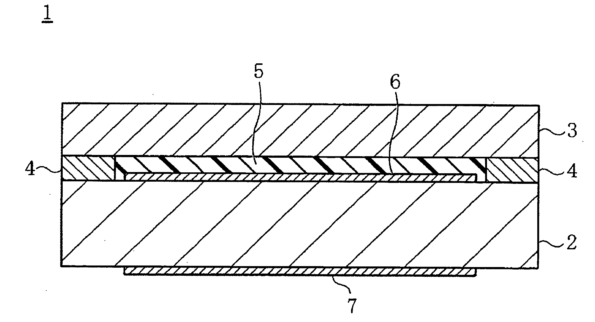
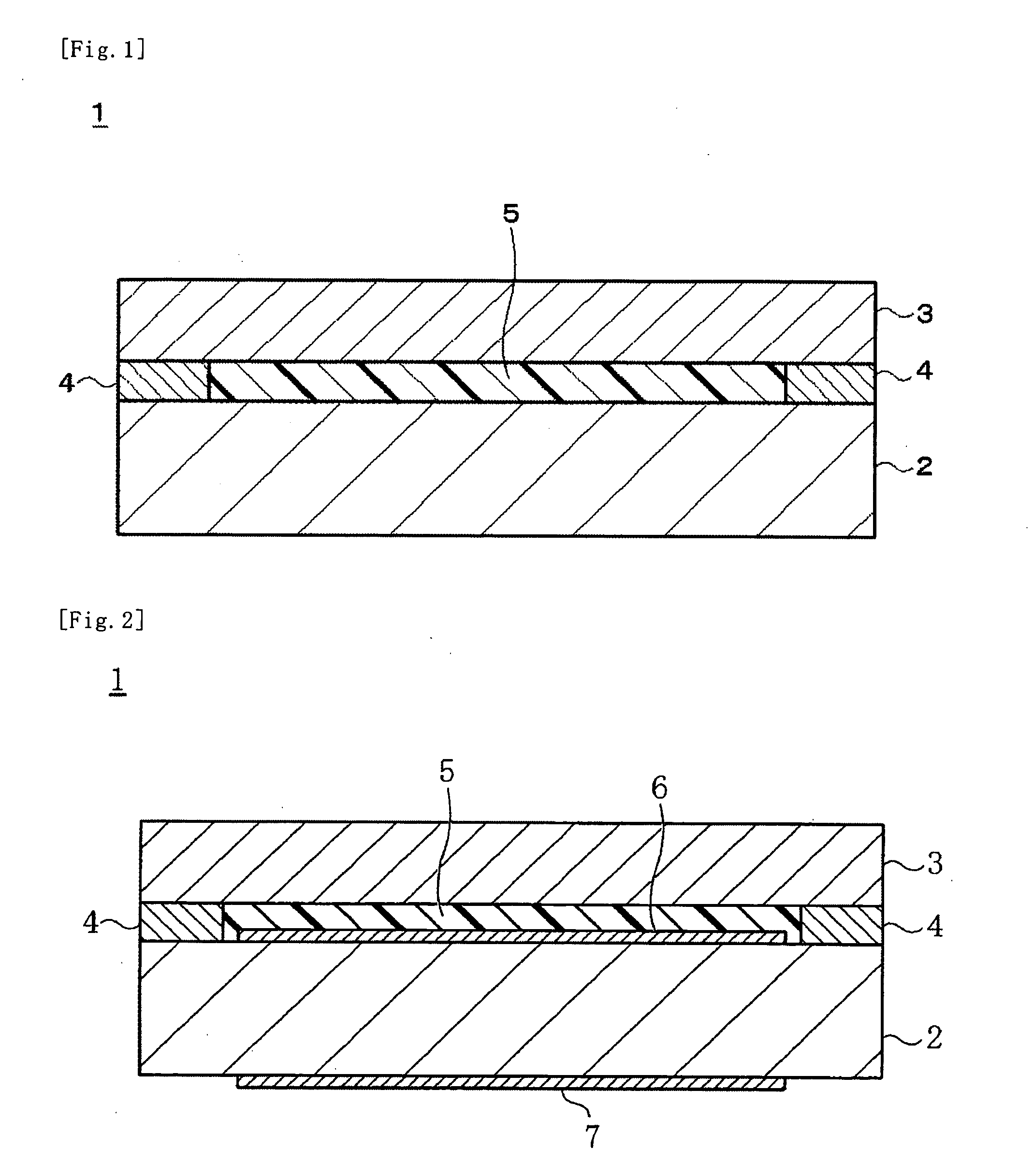
[0019]In the present invention, the cured resin layer arranged between the image display part and the protective part has a light transmittance of 90% or more and a refractive index (nD) of 1.45 or more and 1.55 or less and more preferably, for example, 1.51 or more and 1.52 or less. In this manner, as compared to the case in which air having a refractive index of 1.0 is arranged therebetween, the differences in refractive index at the interface of the image display part and the interface of the protective part are smaller, so that the scattering and attenuation of image light from the image display part can be reduced. Therefore, according to the present invention, the brightness and contrast of the displayed image can be increased, whereby the visibility can be improved.
[0020]In the present invention, the use of a resin composition having a curing shrinkage ratio of 5% or less and yielding a cured product having a storage modulus at 25° C. of 1.0×10⁷ Pa or less can minimize the influence of the stress during cure shrinkage of the resin on the image display part and the protective part. Therefore, almost no distortion occurs in the image display part and the protective part.
[0021]Accordingly, a high brightness and high contrast image can be displayed without display defects.
[0022]In particular, when the image display part is a liquid crystal display panel, display defects such as irregularities in the orientation of the liquid crystal material can be reliably prevented, so that a high quality image can be displayed.
[0023]Moreover, in the present invention, the gap between the image display part and the protective part is filled with the cured resin. This provides high impact resistance.
[0024]In addition, an image display device thinner than the conventional example in which a gap is formed between the image display part and the protective part can be provided.

Problems solved by technology

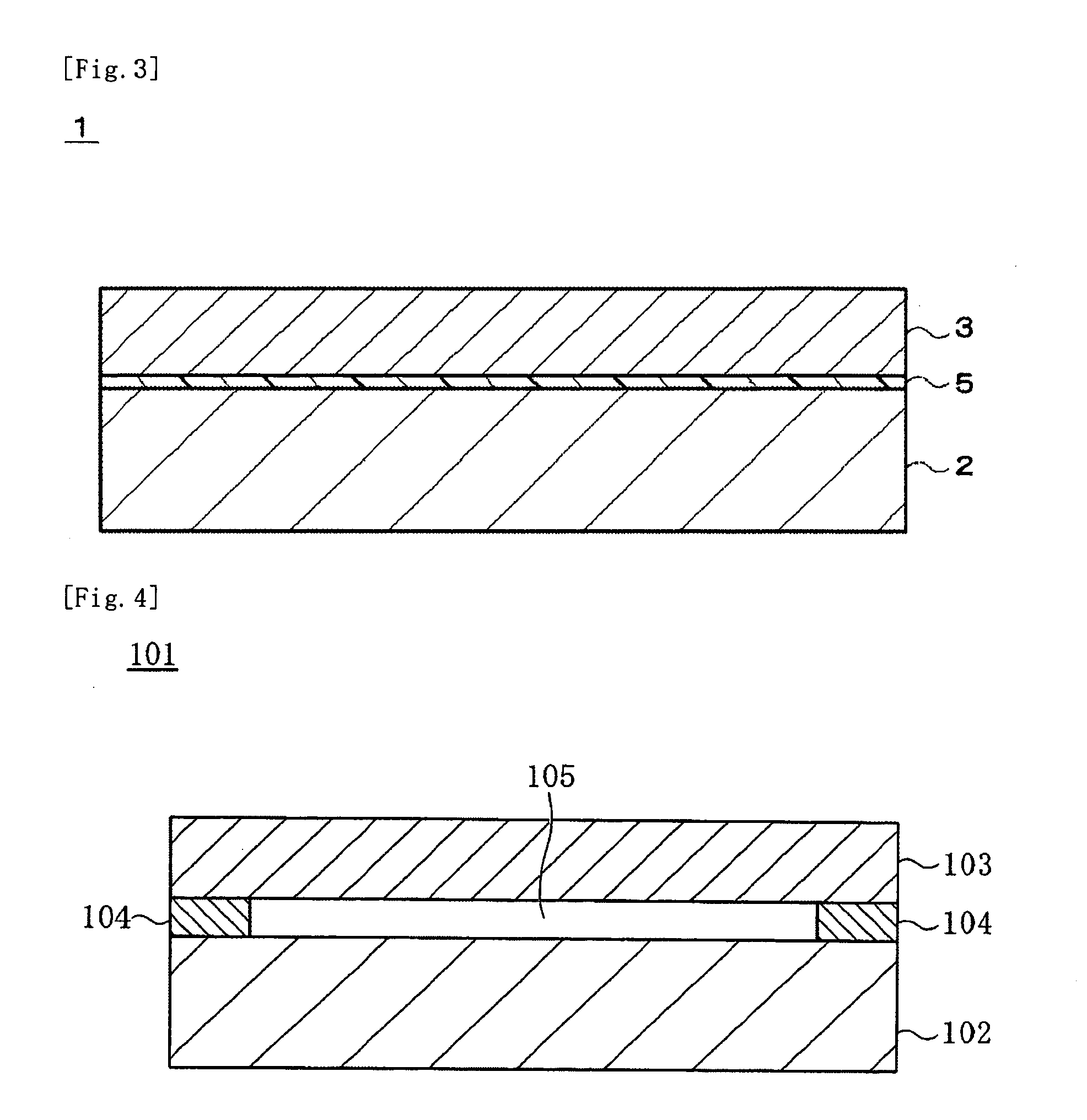
In addition, the presence of the gap 105 also makes it difficult to produce thinner display panels.
However, the stress during cure shrinkage of the cured resin causes deformation of optical glass plates sandwiching the liquid crystal of the liquid crystal display panel.
This results in display defects such as irregularities in the orientation of the liquid crystal material.

Method used


Image

  • Image display device
  • Image display device
  • Image display device

Examples


example 1

[0058]50 Parts by weight of polyurethane acrylate (trade name: UV-3000B, manufactured by Nippon Synthetic Chemical Industry Co., Ltd.), 30 parts by weight of isobornyl acrylate (trade name: IBXA, manufactured by Osaka Organic Chemical Industry Ltd.), 3 parts by weight of a photopolymerization initiator (trade name: IRGACURE 184, manufactured by Ciba Specialty Chemicals Inc.), and 1 part by weight of a photopolymerization initiator (trade name: SpeedCure TPO, manufactured by Nihon SiberHegner K.K.) were kneaded using a kneader to prepare a resin composition of Example 1.

example 2

[0059]70 Parts by weight of an ester compound formed from a maleic anhydride adduct of polyisoprene polymer and 2-hydroxyethyl methacrylate, 30 parts by weight of dicyclopentenyloxyethyl methacrylate, 10 parts by weight of 2-hydroxybutyl methacrylate, 30 parts by weight of a hydrogenated terpene resin, 140 parts by weight of a butadiene polymer, 4 parts by weight of a photopolymerization initiator, and 0.5 parts by weight of a photo polymerization initiator for visible light were kneaded using a kneader to prepare a resin composition of Example 2.

example 3

[0060]100 Parts by weight of an ester compound formed from a maleic anhydride adduct of polyisoprene polymer and 2-hydroxyethyl methacrylate, 30 parts by weight of dicyclopentenyloxyethyl methacrylate, 10 parts by weight of 2-hydroxybutyl methacrylate, 30 parts by weight of a hydrogenated terpene resin, 210 parts by weight of a butadiene polymer, 7 parts by weight of a photopolymerization initiator, and 1.5 parts by weight of a photopolymerization initiator for visible light were kneaded using a kneader to prepare a resin composition of Example 3.


PUM

PropertyMeasurementUnit
light transmittanceaaaaaaaaaa
refractive indexaaaaaaaaaa

Abstract

A thin image display device is provided which is free from display defects caused by the deformation of an image display part and can display high brightness and high contrast images. The image display device includes an image display part 2, a light-transmitting protective part 3 arranged on the image display part, and a cured resin layer 5 interposed between the image display part 2 and the protective part 3. The cured resin layer 5 has a light transmittance in the visible region of 90% or more and a refractive index (nD) of 1.45 or more and 1.55 or less.

Description

TECHNICAL FIELD[0001]The present invention relates to an image display device such as a liquid crystal display device (LCD) used, for example, in a cellular phone, and in particular to an image display device that includes a transparent protective part arranged on an image display part and a cured resin layer arranged between the image display part and the protective part.BACKGROUND ART[0002]One conventional example of such an image display device is a liquid crystal display device 101 shown in FIG. 4.[0003]This liquid crystal display device 101 includes a transparent protective part 103 made of, for example, glass or plastic on a liquid crystal display panel 102, as shown in FIG. 4.[0004]In this display device, to protect the surface of the liquid crystal display panel 102 and a polarizing plate (not shown), a spacer 104 is arranged between the liquid crystal display panel 102 and the protective part 103 to form a gap 105 between the liquid crystal display panel 102 and the protect...

Claims


Application Information

Patent Timeline
Patent Type & Authority Applications(United States)
IPC IPC(8): G02F1/1333
CPCG02F1/133308G02F1/133502G02F2202/28G02F2202/023G02F2201/50G02F1/133331G02F1/1335G02F1/1333C08F290/067C08L51/003C08L2203/20
Inventor SHINYA, YOSHIHISAKAMATA, YUSUKE
Owner DEXERIALS CORP
Why Eureka
Try Eureka