Image-guided therapy delivery and diagnostic needle system

a technology of image-guided therapy and needle system, which is applied in the field of radiation treatment instruments, can solve the problems of long recovery time, side effects, incontinence and impotence,

Active Publication Date: 2010-02-11
UNIVERSITY OF ROCHESTER
View PDF30 Cites 99 Cited by
  • Summary
  • Abstract
  • Description
  • Claims
  • Application Information

AI Technical Summary

Benefits of technology

[0027]A specially designed seed cartridge holder is also included which is compatible with commercial seed cartridge with easy loading and unloading function by the positioning plnger and tightening knob. Easy loading and unloading structure for needles including stylet and cannula, and for sterilizers in the component interference places are also included in this device. The device has compact design for the motion transmission moving stages in which ball screws are also used as bushing shaft for supporting.
[0057]The motorized needle rotation of the second embodiment permits controlled, systematic positioning of the cutting area of the needle in both orientation and depth. Continuous activation of the said motorized mechanisms will result in a “peeling” motion, the extent and shape of which can be controlled by the operating clinician.

Problems solved by technology

However, like other surgeries, such a procedure is invasive and with wounds, and the patient needs a long recovery time, and especially, such surgery often results in side effects, such as incontinence and impotence.
External radiation therapy is seldom used currently because of its excessive irradiation to other organs and tissues other than the prostate gland.
There are still many disadvantages of this system, a long time is needed for a practical and commercial product is obtained.
But they have only translation motion, not suitable for sagittal scanning.
Seed implantation is tedious and costs much operating room time with low efficiency and low accuracy in current art.
There is no a practical system obtained.
Precise placement of needles in soft tissue is challenging because of several reasons such as tissue heterogeneity and elastic stiffness, tissue deformation and movement, unfavorable anatomic structures, needle bending, inadequate sensing, and poor maneuverability.
However, rather than cutting the tissue to enable collection in the needle bore, the thin needle tends to displace the tissue, especially rigid malignant tissue.
Even after repeated attempts, a sufficient amount of tissue might not be obtained.
However, the risk of damage to the tissues that the needle has to traverse to reach the area of pathology, as well as the risks of bleeding, infection and patient discomfort, rise with increasing needle thickness.
Large needle core biopsy needles may also cause significant damage to certain organs, such as the lungs and the spleen.
As with fine needles, displacement of movable tissues, such as breast tissue, is also a problem.
These undesired deformation and movement can cause deflection of the needle and the target resulting in clinical complications such as vital tissue damage, misdiagnosis, under / over dosing with radiation, tumor seeding, etc.
Although the biological tissue relaxes and regains the position partially, there are some organ rotation and deformation which do not recover during surgery and consequently the whole surgical plan becomes erroneous.
Surgery causes trauma to the patient, is often performed without real-time image guidance, and may result in unnecessary removal of healthy tissue and / or geographic miss of cancer.
A common drawback across all these ablation techniques is that tissue cannot be removed from the body in its natural biological state for subsequent histological examination.
Particularly, pathological status of the margin around the ablation is difficult to determine due to burning, making subsequent oncological management of the patient very uncertain.

Method used


Image

  • Image-guided therapy delivery and diagnostic needle system
  • Image-guided therapy delivery and diagnostic needle system
  • Image-guided therapy delivery and diagnostic needle system

Examples


Embodiment Construction

[0089]Preferred embodiments of the invention will be set forth in detail with reference to the drawings, in which like reference numerals refer to like elements throughout.

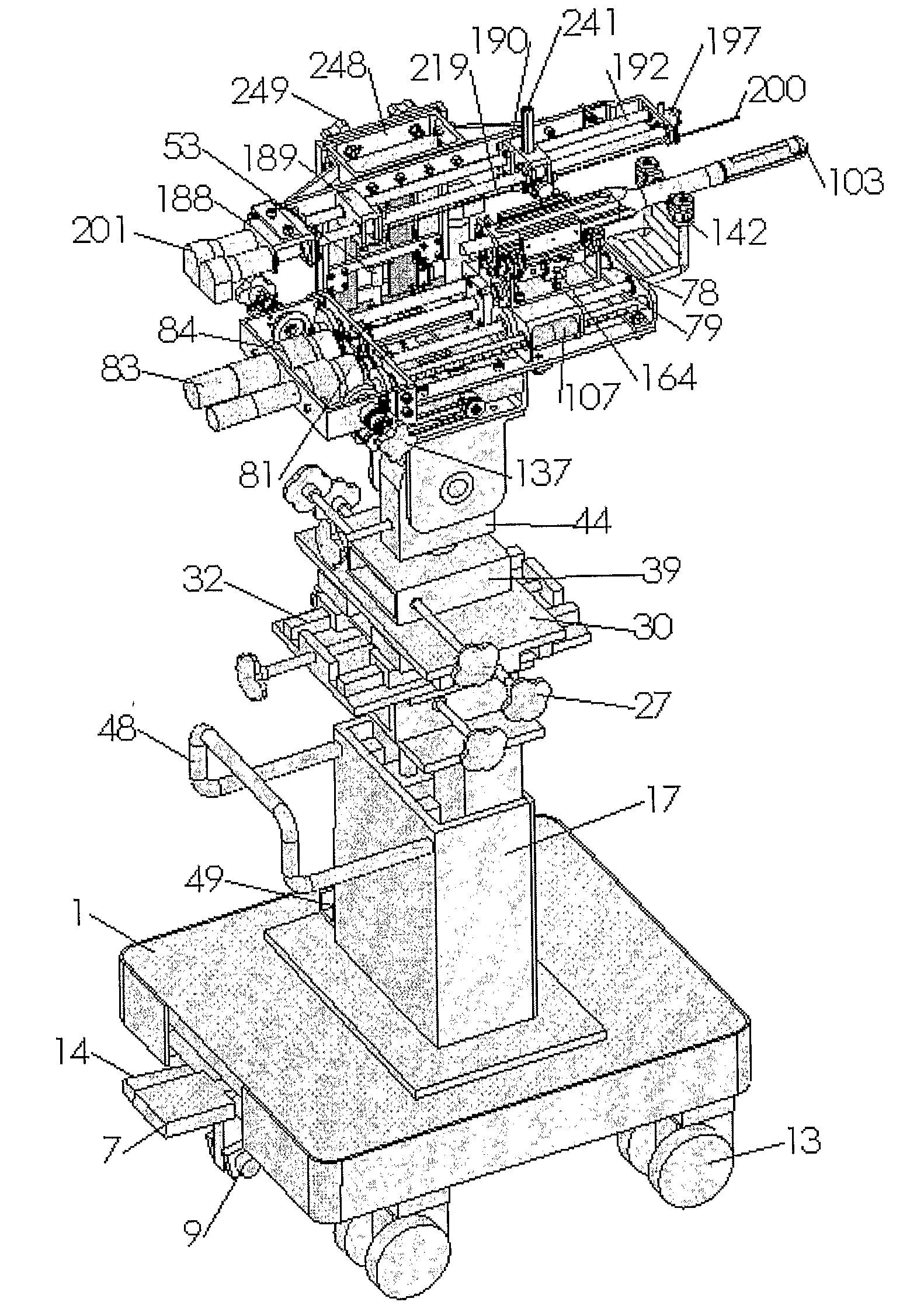
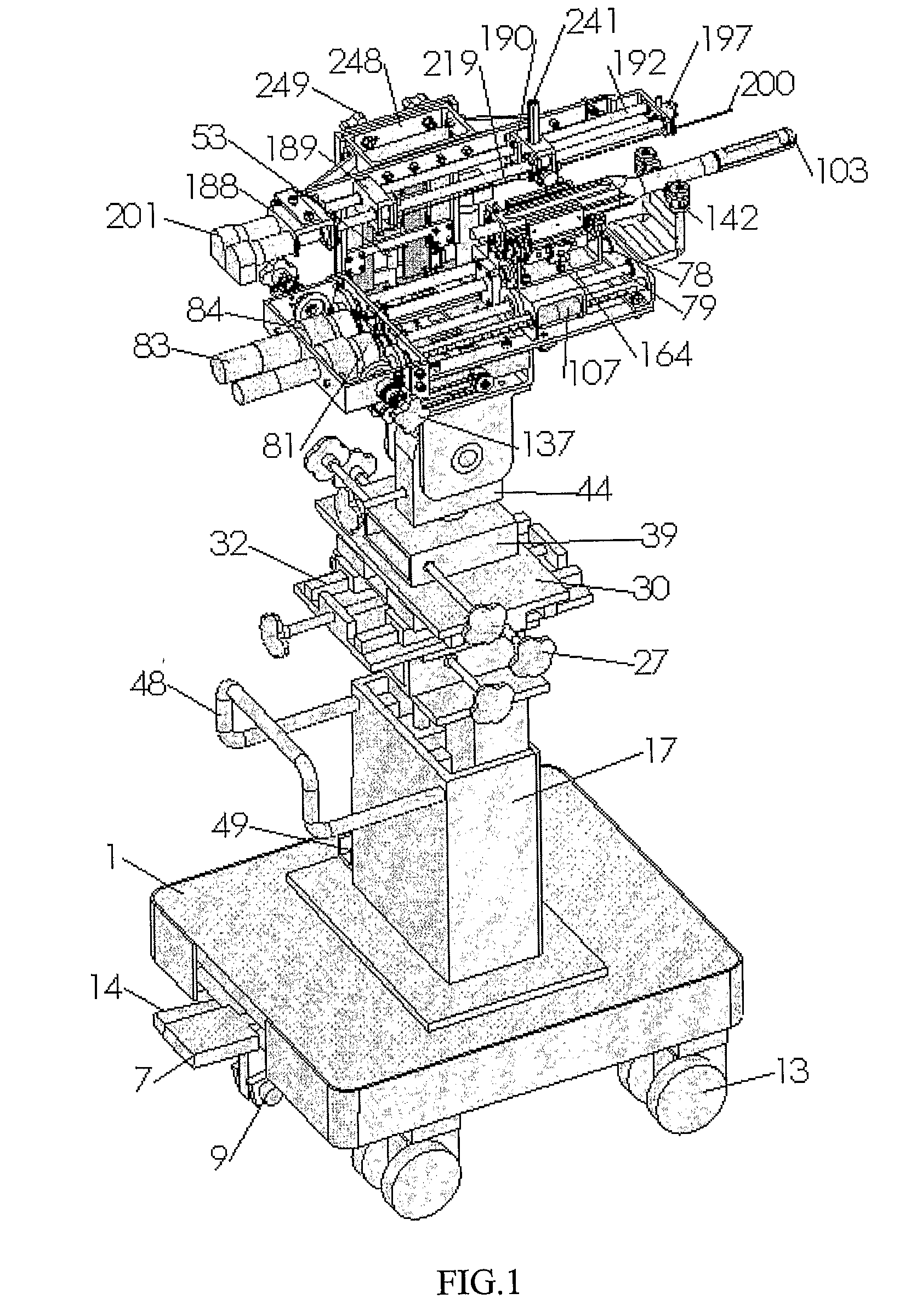
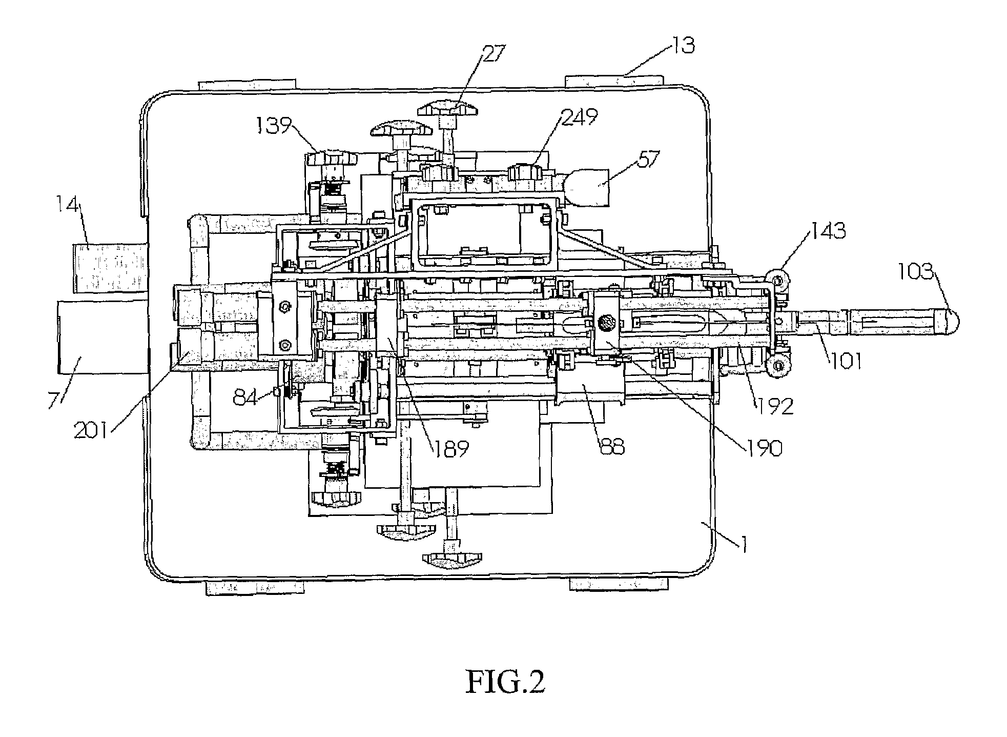
[0090]FIG. 1 to FIG. 4 show the perspective view, top view, side view and back view of 3D assembly of the first preferred embodiment, in which radioisotope seeds are delivered into the patient's body for tumor treatment, for instance, prostate cancer low dose brachytherapy. All the five models are shown including needling mechanism 201, 2DOF robot 53, ultrasound probe driver 83, 5DOF passive platform 32 and the cart 1.

[0091]There are a total of seven DC motors in the system, to obtain cannula insertion with rotation, stylet movement for pushing the seeds into the cannula and implanting in the body, the needling mechanism's left-right and up-down motions for positioning along x and y axis, ultrasound probe's translation and rotation for translational scan and sagittal scan.

[0092]There are a total of three force sen...


PUM


Abstract

An automated system for delivery of seeds or other therapeutic or diagnostic capsules to internal organs of the patient's body for radiation brachytherapy includes a needling mechanism, a 2DOF robot, an ultrasound probe driver, a 5DOF passive platform, and an easy lock cart. The needling mechanism implants radioisotope seeds by its cannula and stylet driven by two moving stages pushed by DC motors with ball screw transmission. Force sensors are included for detecting insertion forces and bending force. In another embodiment, the needle is rotated for insertion into the patient and can also be used for tissue removal for biopsy. The two embodiments are usable together or separately.

Description

REFERENCE TO RELATED APPLICATIONS[0001]The present application claims the benefit of U.S. Provisional Patent Application No. 60 / 741,468, filed Dec. 2, 2005, and of U.S. Provisional Patent Application No. 60 / 818,329, filed Jul. 5, 2006, whose disclosures are hereby incorporated by reference in their entireties into the present disclosure.STATEMENT OF GOVERNMENT INTEREST[0002]The work leading to the present invention was supported in part by the National Cancer Institute under Grant No. R01 CA091763 and Grant No. R33 CA107860. The government has certain rights in the invention.FIELD OF THE INVENTION[0003]The present invention relates generally to the field of devices used in the radiation treatment instruments. More specifically, the present invention relates to the automated seed delivery system of radiation therapy, for example, the brachytherapy of low dose radiation treatment of prostate cancer. The present invention also relates generally to the field of diagnosis and therapy by ...

Claims


Application Information

Patent Timeline
Patent Type & Authority Applications(United States)
IPC IPC(8): A61M36/12A61B19/00A61B8/00
CPCA61B10/0233A61B2010/0208A61N2005/1011A61N5/1027A61B2019/464A61B2090/064
Inventor YU, YANNG, WAND SINGPODDER, TARUNLIAO, LYDIAZHANG, YONGDE
Owner UNIVERSITY OF ROCHESTER
Why Eureka
Try Eureka