Nanosecond pulse generator

a generator and nanosecond technology, applied in the field of pulse generators, can solve the problems of low repetition rate, physical largeness, cell death,

Active Publication Date: 2010-02-18
ALFRED E MANN INST FOR BIOMEDICAL ENG AT THE UNIV OF SOUTHERN CALIFORNIA
View PDF11 Cites 52 Cited by
  • Summary
  • Abstract
  • Description
  • Claims
  • Application Information

AI Technical Summary

Benefits of technology

[0018]The switch of the pulse generator of the instant invention may have a turn-on time of less than 100 nanoseconds. This switch may be a metal-oxide semiconductor field effect transistor (MOS

Problems solved by technology

Permanent openings may result in cell death.
Such shorter pulses with a field strength varying in the range of 1 MV/m to 10 MV/m may trigger apoptosis or programmed cell death.
However, they may be physically large and have only a low repetition rate.
They may also have only a relatively short

Method used


Image

  • Nanosecond pulse generator
  • Nanosecond pulse generator
  • Nanosecond pulse generator

Examples


example 1

Resonant Network Design

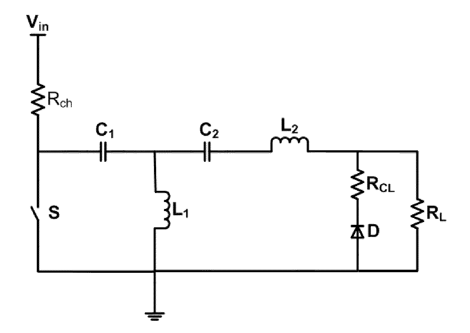
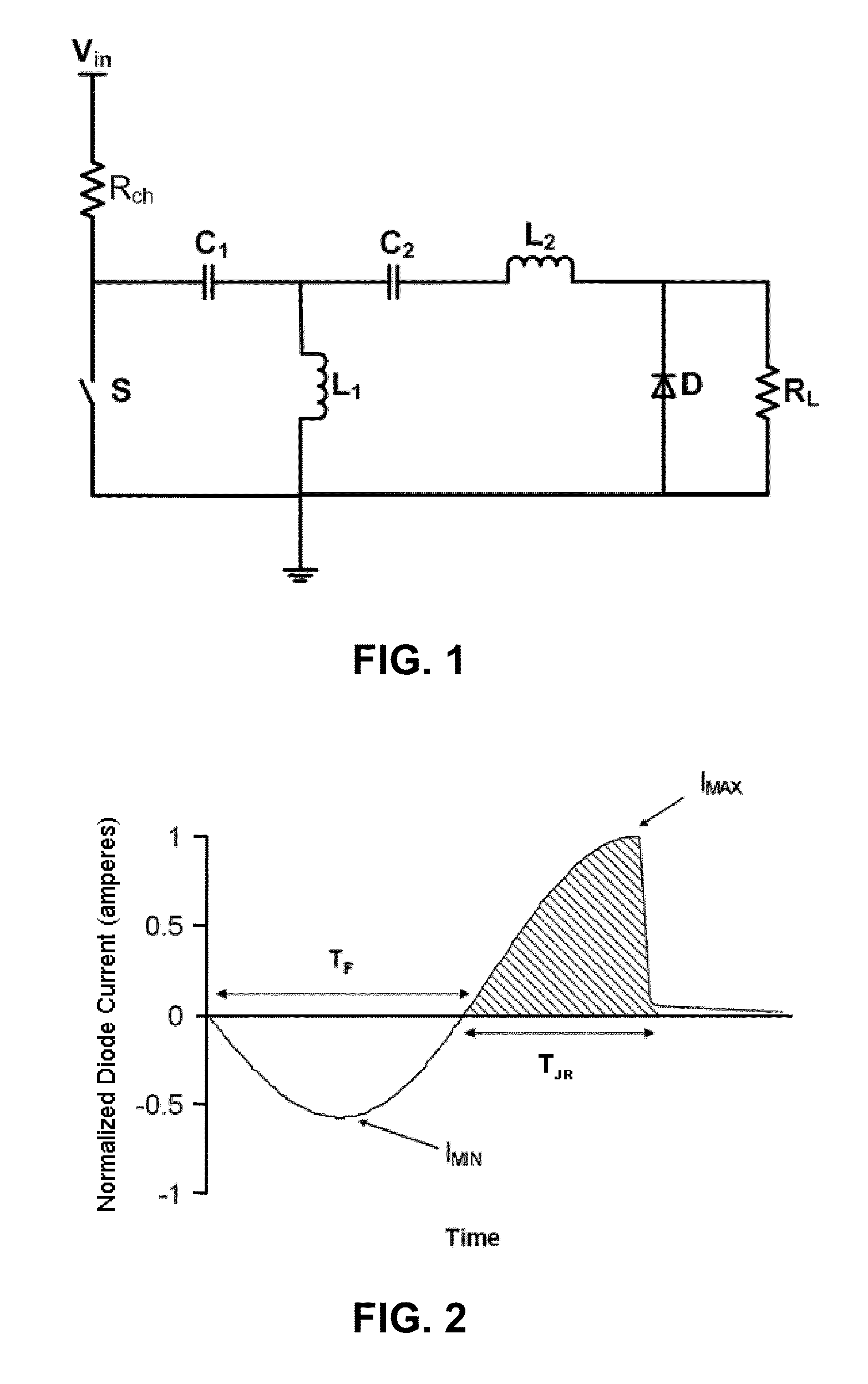
[0070]In this example, the values of the capacitors and inductors may be determined by using a mathematical model for the circuit shown in FIG. 1 as follows. The diode D may be approximated as lossless with a given junction recovery time of about 50 nanoseconds. Then, the forward biased diode may be modeled as an ideal voltage source with a voltage equal to the forward voltage of the diode. This model may be valid until the reverse current flows through the diode for a period equal to the junction recovery time. At this time the conductivity of the lossless diode instantaneously may go to zero. Since the forward biased diode may be modeled as having zero impedance, the diode may be replaced by a short circuit to derive a mathematical model for the current. This expression may be used as a guide to choose inductance and capacitance values that produce an appropriate current to ensure proper switching of the diode (i.e. substantially satisfying IMAX=2*IMIN). The...

example 2

Switch S

[0073]In this example, a variety of solid state switches were tested to determine a switch that may be suitable to use for the construction of the pulse generator of the instant invention. Five different commercially available switches were purchased: one IGBT type switch (rated at 60 amperes, model number GPS60B120 KD) from International Rectifiers (El Segundo, Calif.); three MOSFET type switches (first one rated at 13 amperes, model number APT13F120B; second one rated at 28 amperes, model number APT135B2FLL; and third one rated at 37 amperes, model number APT37M100L) from Microsemi Corporation (Irvine, Calif.); and one SCR type switch (model number SK065K) from Littelfuse (Chicago, Ill.). These switches were evaluated by constructing a circuit shown in FIG. 1 with L1=L2=about 250 nH and C1=C2=about 12 nF. The diode D was replaced with a short wire. The short circuit current was measured with a current transformer. The peak of the forward current was recorded for each switc...

example 3

Construction of a Pulse Generator and Pulses Obtained by Using this Generator

[0077]In this Example, two pulse generators were designed and built by using the mathematical model described in Example 1. First pulse generator was designed to provide a pulse with a length of about 5 nanoseconds and the other with a length of about 2.5 nanoseconds.

[0078]The pulse generators were constructed by using commercially available EIC CN25M diodes or MURS2510 diodes (both about 1 kV, about 25 amperes DC rating). EIC CN25M diodes had about 50 nanoseconds junction recovery time and MURS2510 diodes about 100 nanoseconds. Both diodes had very short snap-off times. To obtain a pulse with an amplitude of about 5.0 kV with a current of about 100 amperes, five diodes were connected in series to form a stack and five of these stacks were connected in parallel, which formed the diode array.

[0079]It was determined that, for the 5 nanosecond pulse generator, L1=L2=about 260 nH and C1=C2=about 12 nF and that,...


PUM


Abstract

This invention relates to a pulse generator circuit for delivering a short high current pulse to a load. This pulse generator comprises a junction recovery diode, a switch, a first resonant circuit and a second resonant circuit. The diode may be configured to store charges in its depletion layer when there is a forward flow of a current and to rapidly switch open after the depletion layer is discharged by a reverse flow of a current. After the diode rapidly switch opens, the pulse generator may provide a reverse current to the load. This pulse generator may be configured to generate at least one pulse that is having a length of no more than 100 nanoseconds at the full-width-at-half-maximum and an amplitude of at least 1 kilovolt. Electrodes may be connected to the pulse generator to deliver one pulse or plurality of pulses to biological cells such as tumor cells.

Description

CROSS-REFERENCE TO RELATED APPLICATIONS[0001]This application is based upon and claims priority to U.S. Provisional Application Ser. No. 61 / 128,708, filed May 23, 2008, attorney docket no. 64693-217, entitled “Nanosecond Aircore Pulse Generator with Scalable Pulse Amplitude,” the entire content of which is incorporated herein by reference.STATEMENT REGARDING FEDERALLY SPONSORED RESEARCH[0002]This invention was made with government support under the U.S. Air Force Office of Scientific Research Grant Nos. F49620-02-1-0073. The government has certain rights in the invention.FIELD OF THE INVENTION[0003]This invention relates to pulse generators and, more particularly, to pulse generators that may be used for electroperturbation of biological cells.BACKGROUND OF THE INVENTION[0004]Ultra-short, high-field strength electric pulses may be used in the electroperturbation of biological cells. For example, these electric pulses may be used in treatment of human cells and tissue including tumor...

Claims


Application Information

Patent Timeline
IPC IPC(8): H03K3/02
CPCH03K3/57H03K5/12H03K17/74H03K5/07C12M35/02
Inventor SANDERS, JASONKUTHI, ANDRASGUNDERSEN, MARTIN A.MOORE, WILLIAM HENRY
Owner ALFRED E MANN INST FOR BIOMEDICAL ENG AT THE UNIV OF SOUTHERN CALIFORNIA
Why Eureka
Try Eureka