Wide-bandwidth chirped fiber bragg gratings with low delay ripple amplitude

a fiber bragg grating and wide-bandwidth technology, applied in the field of chromatically dispersing lightwave signals, can solve the problems of introducing errors in detected data streams, limiting the reach of data rate for a single optical channel, and reducing the performance of the system, so as to achieve low delay ripple amplitude and not exhibit large fluctuations in system performance penalty across bandwidth

Inactive Publication Date: 2002-11-07
PROXIMON FIBER SYST
View PDF0 Cites 69 Cited by
  • Summary
  • Abstract
  • Description
  • Claims
  • Application Information

AI Technical Summary

Benefits of technology

[0019] In another aspect, the present invention relates to a method and apparatus for fabricating long length FBGs. In accordance with this aspect of the invention, the fiber being written on is translated with .about.1 ppm (10.sup.-6) velocity control. This is preferably accomplished by placing the fiber into a helical groove on a spool that is mounted to a rotary spindle. The spindle is rotated at a constant velocity, which is preferably regulated by a large flywheel. The groove on the spool acts like a thread on a screw so that, as the spindle turns, a linear stage is used to track the laser beam on the fiber, in a manner analogous to cutting threads on a lathe. Gratings that are tens of meters long can be fabricated with this method.

Problems solved by technology

However, this approach is limited in that the data rate for a single optical channel will eventually reach practical limitations.
This effect, called chromatic dispersion, broadens the pulse to the point that it eventually interferes with neighboring pulses in a pulse train and introduces errors in the detected data stream.
These compensation modules are bulky, and due to the fiber design, suffer high optical attenuation and increased optical nonlinear effects.
However, DCF is used today since no serious alternative exists.
As a practical matter, long length gratings for dispersion compensation are not available, since extreme tolerances must be maintained to manufacture quality long length gratings.
Fabrication errors in chirped gratings create ripples in the group delay curve and thus inaccuracies in the dispersion correction.
However, the magnitude of the ripple needed to make a useful FBG dispersion correction device has not been verified.
Given that the silicon-oxygen inter-atomic spacing in glass is .about.160 pm, it has been widely believed that holding these tolerances during grating inscription is not possible, and that fiber fabrication tolerances are limiting the quality of the gratings that they produce.
The range of motion of available high-precision staging has limited the length these FBGs.
Several groups have adapted stitching methods to make chirped long length gratings, but stitching errors have caused these gratings to have delay ripple amplitudes that are far too large for use as dispersion compensators in optical communications systems.
The accuracy of location measurements is limited by the motion stage encoder--usually interferometer based, which is susceptible to several degradations, such as interpolator inaccuracies, noise in edge detection electronic circuitry, and random fluctuations in received interpolator-laser light.
The high-frequency ripple adds an intra-pulse distortion to a communication signal that is difficult to correct, thus the high-frequency ripple is considered more critical than the low-frequency ripple, which merely adds a slight error to the dispersion correction.
Establishing a correlation between delay ripple amplitude and optical system performance has been confusing because different groups measure DCGs in different manners and, often, are not explicit about their measurement procedures.
Although several studies have demonstrated that DCGs could be used as dispersion compensators for a single communication channel, useful wide bandwidth devices have not been demonstrated, mainly because the delay ripple amplitude of these devices was too large.
Widely chirped DCGs with several WDM channels operating across their bandwidth have been demonstrated, but because the wavelength of the transmitting laser in the communication system needs adjustment in all of these studies to obtain reasonable performance, these DCGs proved to have only very narrow sections of usable bandwidth across their entire bandwidth.
If a wideband DCG with a large delay ripple is useful only over a very narrow range as a dispersion compensator, then the utility of this widely chirped device is lost.
Others have demonstrated DCGs in laboratory systems where DCGs have been used to correct the dispersion in several channels of a communication system, but a DCG that covers only part of a communication band has limited appeal, since the system must be specially engineered to accommodate such a device.
But these DCF designs don't exactly match the dispersion characteristics of their intended fiber and thus leave a residual dispersion that accumulates over multiple spans of transmission fiber.
Since DCF designs can be complicated and difficult to manufacture, several transmission fibers do not yet have a matching DCF solution, and some fibers, due to their complex dispersion characteristics, seem unlikely that a perfectly matching DCF design is possible across a wide bandwidth.

Method used


Image

  • Wide-bandwidth chirped fiber bragg gratings with low delay ripple amplitude
  • Wide-bandwidth chirped fiber bragg gratings with low delay ripple amplitude
  • Wide-bandwidth chirped fiber bragg gratings with low delay ripple amplitude

Examples


example 1

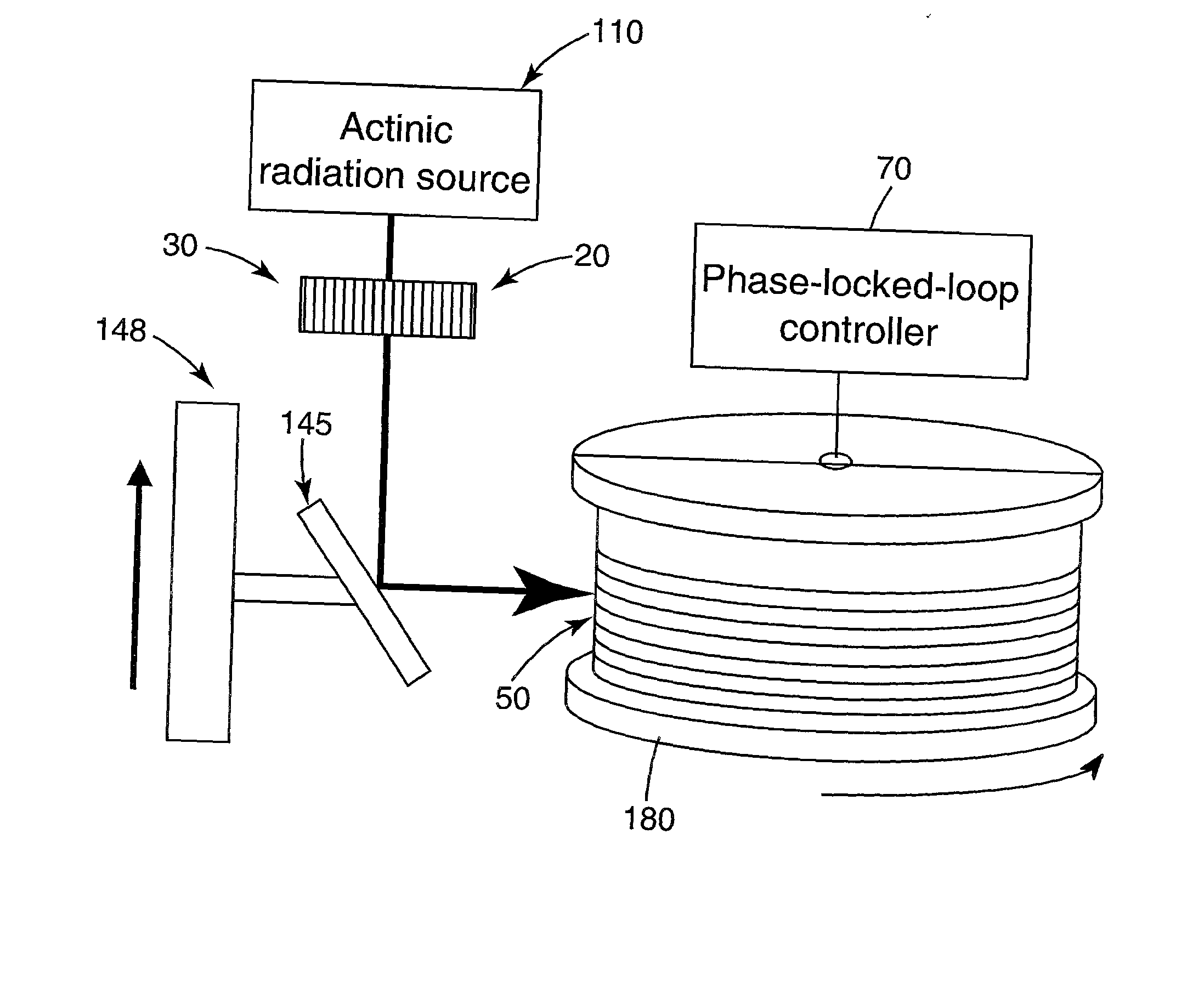
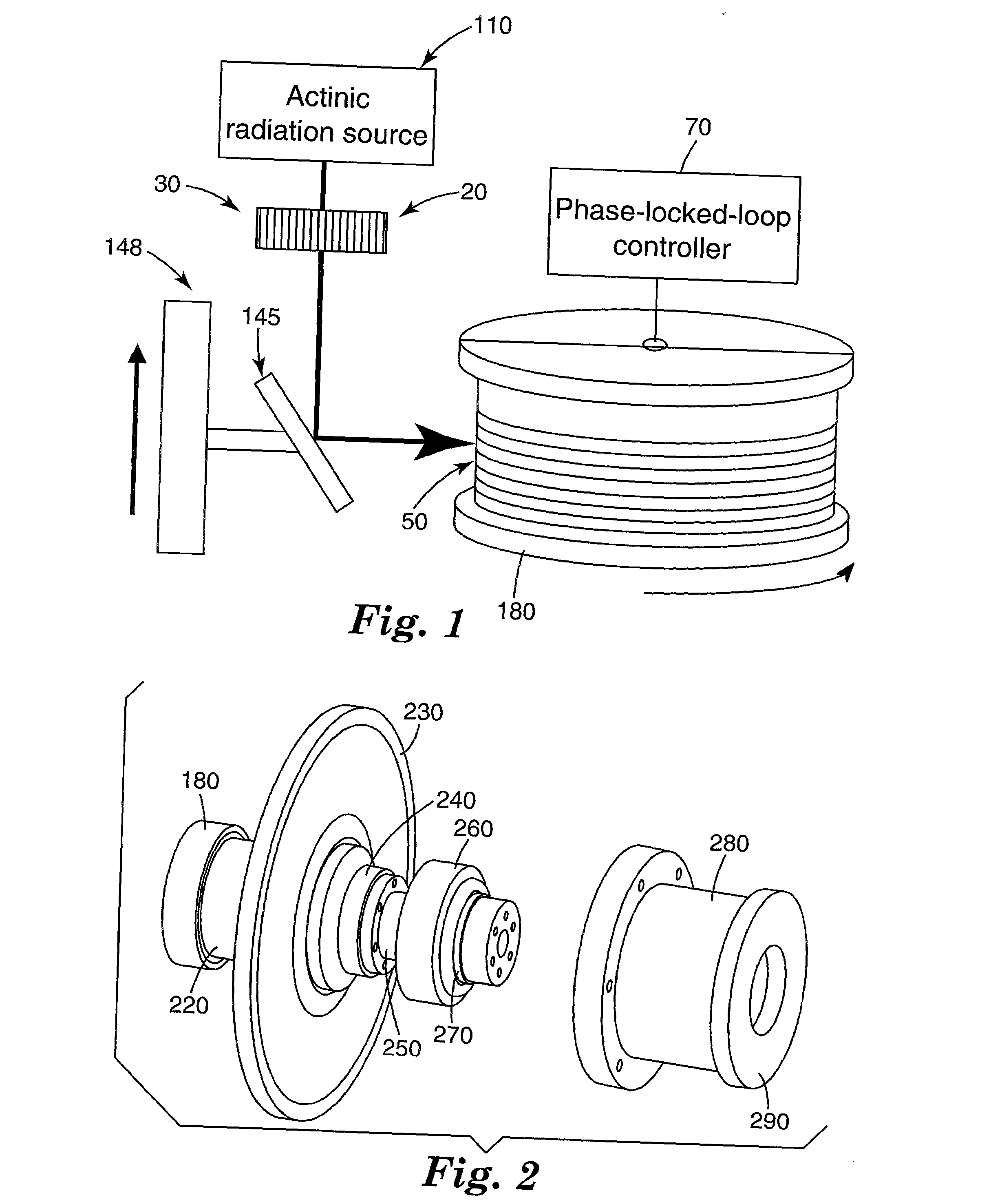
[0043] This example illustrates the effect of increasing the rotational inertia, and hence the angular momentum, of the spindle used in the DCG fabrication system.

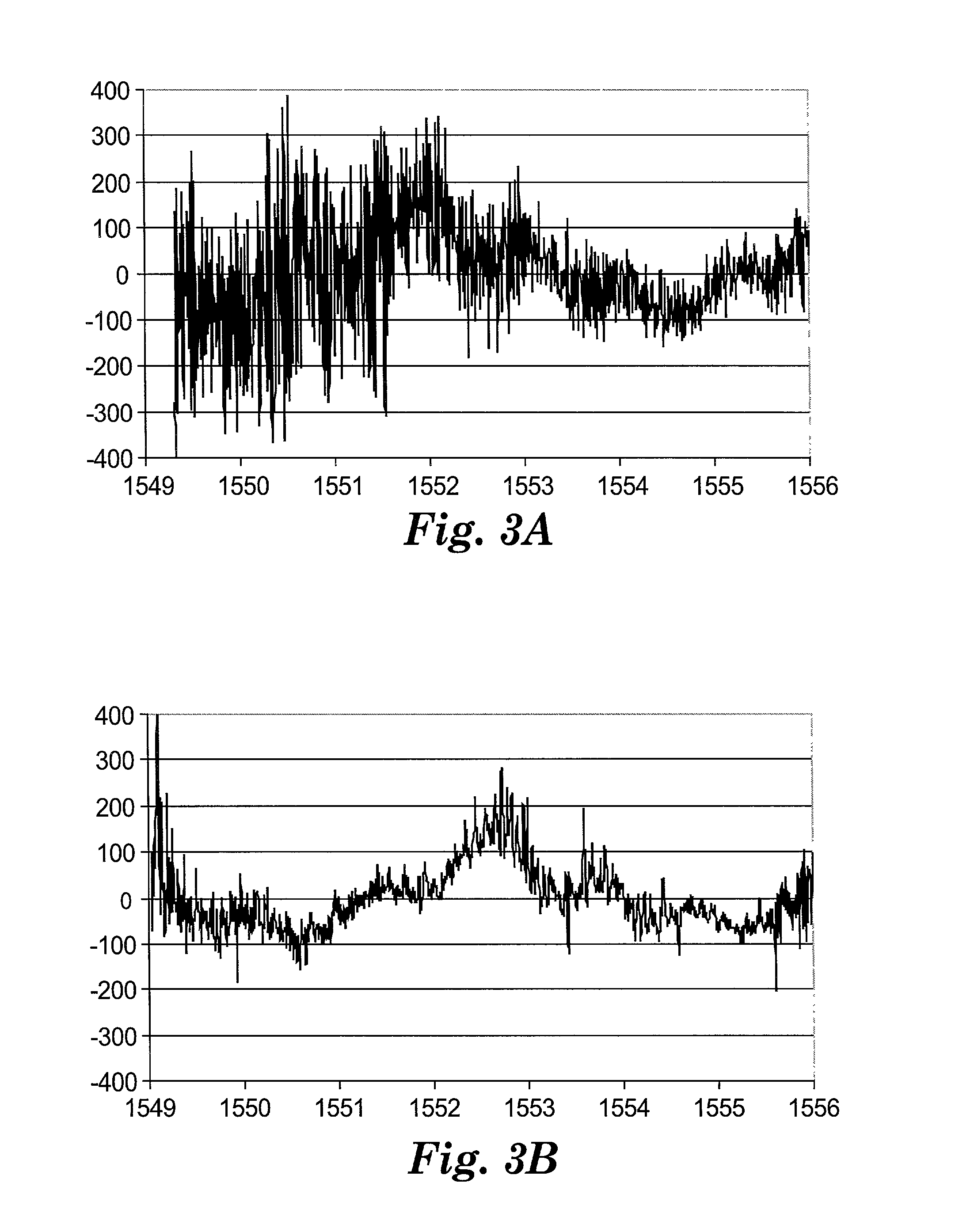
[0044] Two chirped FBGs were written, and their delay ripple amplitude was analyzed. The fabrication system of the first FBG comprised an induction motor with a smooth-walled rotor supported by an air bearing spindle. The spindle was controlled to rotate at a constant velocity with phase-locked-loop (PLL) electronics that followed a moir-effect rotary encoder. A spool with a helical groove to hold the optical fiber was also mounted to the air-bearing spindle. A spectrum of the delay ripple is shown in FIG. 3a. The delay ripple amplitude was hundreds of picoseconds. The rotaional inertia of the first system was .about.0.5 g m.sup.2.

[0045] The fabrication of the second gratings was the same as the first, but in this case the rotational inertia of the system was increased 40 times by adding a 40-cm-diameter flywheel to the sy...

example 2

[0047] A measurement of a DCG delay ripple with the modulation phase-shift method can vary depending on the modulation frequency, as shown in FIG. 4. If the measurement is made at 1 GHz, a ripple with {fraction (1 / 2)} the amplitude of that measured with a 100 MHz signal may be determined. It has been found that measuring the devices with a modulation frequency of <200 MHz gives consistent results. In some cases where the periodicity of the ripple is very fine, a frequency of <50 MHz is needed. For the measurements reported herein, a modulation frequency of 200 MHz was used as a standard.

example 3

[0048] This example further illustrates the improvements possible in delay ripple amplitude through the use of increasing the angular momentum of the spindle.

[0049] The fabrication system detailed in Example 1 was further improved by installing a heavier flywheel attached to the system of inertia .about.650 g cm.sup.2. The gratings were also written at faster rotational speeds to further increase the angular momentum of the fabrication system. The resulting FBGs exhibited delay ripple amplitudes of less than .+-.30 ps over bandwidths greater than 1 nm. The reflection, delay in reflection, and delay ripple of such a grating is shown in FIGS. 5 & 6.


PUM


Abstract

A device including a chirped Bragg grating, said grating having (a) a reflection bandwidth having a full-width at half maximum that is greater than 6 nm, and (b) a reflection delay ripple amplitude of less than .+-.50 ps.

Description

FIELD OF THE INVENTION[0001] The present invention relates generally to a device used for chromatically dispersing lightwave signals in fiber optics, and more specifically to a wide-bandwidth chirped fiber Bragg grating that has a low delay ripple amplitude.BACKGROUND OF THE INVENTION[0002] Modem communication system providers are striving to increase the capacity of their systems to satisfy the rapidly growing exchange of information around the world. Increasing the data rate of a single wavelength channel is one strategy to increase the throughput on optical fibers. However, this approach is limited in that the data rate for a single optical channel will eventually reach practical limitations. An important strategy to further increase the available bandwidth is to add multiple wavelength channels. Multiple wavelength systems are referred to as being wavelength division multiplexed (WDM).[0003] Optical communications systems are available with single-channel data rates at 10 Gbit / s...

Claims


Application Information

Patent Timeline
Patent Type & Authority Applications(United States)
IPC IPC(8): G02B6/122G02B6/02G02B6/10G02B6/26G02B6/34
CPCG02B6/02085G02B6/02138G02B6/02152G02B6/02147G02B6/02142
Inventor BRENNAN, JAMES F. IIIHERNANDEZ, EDWARDVALENTI, JOHN A.SINHA, PRANAY G.MATTHEWS, MICHAEL R.ELDER, DALE E.BEAUCHESNE, GERARD A.BYRD, CHAD H.
Owner PROXIMON FIBER SYST
Why Eureka
Try Eureka